The simplest attenuator for audio card
In amateur radio engineering, namely in the design of low-frequency amplifiers, it is very convenient to use a computer for measurements.
Professional instrumentation costs a lot of money, whereas the sound card is available in almost any home computer. Together with affordable and diverse software, we get a handy tool for removing all the main characteristics: frequency response (amplitude-frequency response), THD (harmonic distortion level), signal-to-noise ratio and spectrogram.

The only inconvenience is too sensitive audio card input,
on which it is impossible to give a signal exceeding the voltage of 0.5-1.5 volts.
And here comes the attenuator.
')
It can (and should) be collected independently. There is nothing tricky in this experience, but for those who take the first steps in reinforcement, the material will be useful.
The attenuator is a passive device and in fact, applied to our case, is a resistive voltage divider. Its function is to attenuate the signal level (ac audio voltage) according to specified parameters. Let's define these parameters.
It is necessary to apply a signal to the line input of the audio card, taken from the output terminals of the power amplifier, without overloading the audio card. For convenience, we set the value of the output voltage of the attenuator to 0.775v RMS . Such a voltage will be acceptable for any modern audio card with a linear input, besides, the value of 0.775v is usually chosen as the reference level ( 0dBu ) when measuring absolute values in decibels.
I highly recommend reading about measurements and decibels “What we measure?” By Mikhail Chernetsky (there is a link to the publication on the website of the Sound Engineer at the end of the post [1] , but it's much more comfortable for the eyes to read on the author’s website )
The input voltage on the attenuator will be chosen in such a way that it corresponds to the power dissipated at an equivalent load of 8 Ohm, and is equal to 1W.
For the RMS value of voltage (RMS), the following formula for calculating the power is true:

Some consider the power of a sinusoidal signal according to the formula P = U a ^ 2 / 2R , confusing the amplitude value of the voltage with the rms. Maybe they have an oscilloscope on hand for these measurements (?!), we use a TrueRMS voltmeter and know the difference (and dependence) between the amplitude and root-mean-square voltage values (if you catch yourself thinking that you forgot and you need to refresh your memory urgently - let's go straight to Radiocoot [2] ).
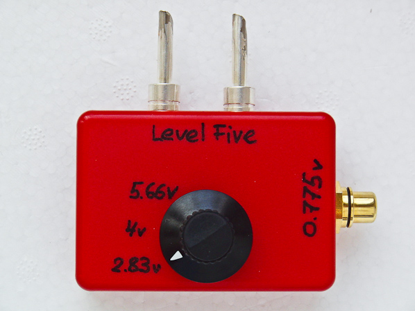
According to the above formula, we find the value 2.83v (for 1W), 4v (for 2W) and 5.66v (for 4W). Usually, to measure the characteristics of a low-power amplifier, these values are quite sufficient, but if larger values are required, you can easily calculate them yourself.
Do not be surprised at such “small” power values - for example: a single-ended tube amplifier of your humble servant (mode of operation “A” class) with a power of 2W (!) “Swings” healthy floor acoustics without any difficulty (according to the few requests from habrachitechitel I in the process of thinking about the article about its construction, but for the time being I decided to probe the interest in the topic by publishing this material - there is a connection with computers at least).
So, we have the input data - you can go to the calculation.
In general, the formula for calculating the divider without load is as follows:
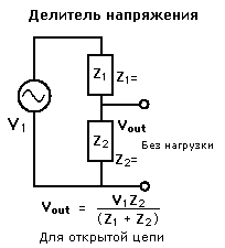
The only thing to be taken into account is that the value of the resistor Z 1 must be chosen 3-4 orders of magnitude greater than the equivalent load of 8 Ohm, so that for the amplifier the connection of the attenuator remains “unnoticed” (high-resistance, relative to the output of the amplifier, the attenuator input practically does not change the value of the equivalent load resistance , since it is connected in parallel to a load of 8 ohm - we recall the rule of addition of resistors connected in parallel [3] ).
For convenience, choose Z 1 = 20 kOhm , then the nominal value of the lower resistor ( Z 2 ) is calculated by the formula:
We get Z 2 = 0.775 * 20000 / 2.828-0.775 = 7550 Ohm
Similarly, we calculate the ratings for other input voltages: 4v (for 2W) and 5.66v (for 4W).
Meticulous readers probably already noticed that we nowhere take into account the input impedance of the audio card. And the thing is: almost any sound card will change the resistance of the resistor Z 2 , since it will actually be a resistance connected in parallel to it. What does this mean for us? It means that the output voltage of our attenuator will be somewhat less than the 0.775v (sic!) Predicted in the calculations.
"So it is necessary to measure the resistance of the line input, business something!" - You say. But everything is not so simple: a sound card has a capacitor at the input - a normal multimeter does not measure the input impedance of the card. Here we need a generator and an oscilloscope, not all have them, so in this article we do not take into account the input impedance of the audio card when calculating.
However, in case you already know the line-in impedance of your sound card (for example, it is indicated in the specification), I’m writing a formula that takes into account the input impedance of the audio card when calculating the attenuator:

where Z L is the resistance of the line input of the audio card.
The scheme uses graphical designations of the principles of authorship of Sergey Komarov. I recommend to download [5] and use.
We will need banana connectors (2pcs.) (Or other connectors compatible with your amplifier), one RCA connector, a rotary switch and a knob for it (1/4 "), as well as resistors (see denominations in the scheme).
As a case, I had to buy a plastic case in Chip and Dipe for a frenzy of 90 rubles. But he was very fit in size (65x45x22mm).

Choosing a rotary switch is a matter of taste. You can choose the cheapest Chinese, and you can - quality. I chose the 2nd option and ordered an expensive Grayhill 71BD36-01-1-AJN. The resource is 50,000 turns, the rotor's contacts are gold-plated (30 microinches is a curious unit of thickness of the coating ), "military acceptance", real American production. I never agitate, but I cite a link to datasheet [4] .
The switch has 10 positions, but we only need three.
Ideally, you still need a minimum of tools: a ruler or a caliper, a drill, a polyhedron key (to fasten the handle to the shaft).
Earthen tire is better to make of copper monozhily. I didn’t have a suitable diameter at hand, and I twisted it from copper conductor (22AWG) and tinned it with lead-free silver-containing solder.
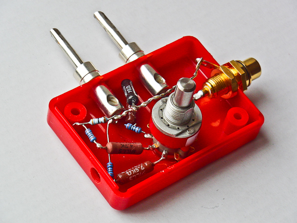
Resistors can take any, 1-2 watts. Ideal to choose wire or foil - they have minimal noise. I chose non-inductive wire mills.
Soldering to the contacts is very convenient - they have a big step, and the switch body is made of thermoplastic and you can be safe from damaging it with a hot soldering iron tip.
After fixing the connectors and soldering the resistors, you can close the case with a cover (I fixed all the parts in the case half), tighten the switch nut, put two screws (attached to the case), fix the handle on the shaft and sign the input voltages on the case.
The finish! You can begin to measure, but this is a topic for a separate article.
[1] “What do we measure?” (Archive of “Sound producer” magazine)
[2] "Measurement of the output power of audio amplifiers" (Training from Radiookot)
[3] Parallel connection of resistors (resistor page on Wikipedia)
[4] Datashit on Grayhill 71st series
[5] “Good old graphics of schematic diagrams” (author Sergey Komarov)
Professional instrumentation costs a lot of money, whereas the sound card is available in almost any home computer. Together with affordable and diverse software, we get a handy tool for removing all the main characteristics: frequency response (amplitude-frequency response), THD (harmonic distortion level), signal-to-noise ratio and spectrogram.
The only inconvenience is too sensitive audio card input,
on which it is impossible to give a signal exceeding the voltage of 0.5-1.5 volts.
And here comes the attenuator.
')
It can (and should) be collected independently. There is nothing tricky in this experience, but for those who take the first steps in reinforcement, the material will be useful.
The attenuator is a passive device and in fact, applied to our case, is a resistive voltage divider. Its function is to attenuate the signal level (ac audio voltage) according to specified parameters. Let's define these parameters.
Task
It is necessary to apply a signal to the line input of the audio card, taken from the output terminals of the power amplifier, without overloading the audio card. For convenience, we set the value of the output voltage of the attenuator to 0.775v RMS . Such a voltage will be acceptable for any modern audio card with a linear input, besides, the value of 0.775v is usually chosen as the reference level ( 0dBu ) when measuring absolute values in decibels.
! dB u - , () ( . unloaded ).I highly recommend reading about measurements and decibels “What we measure?” By Mikhail Chernetsky (there is a link to the publication on the website of the Sound Engineer at the end of the post [1] , but it's much more comfortable for the eyes to read on the author’s website )
The input voltage on the attenuator will be chosen in such a way that it corresponds to the power dissipated at an equivalent load of 8 Ohm, and is equal to 1W.
For the RMS value of voltage (RMS), the following formula for calculating the power is true:
Some consider the power of a sinusoidal signal according to the formula P = U a ^ 2 / 2R , confusing the amplitude value of the voltage with the rms. Maybe they have an oscilloscope on hand for these measurements (?!), we use a TrueRMS voltmeter and know the difference (and dependence) between the amplitude and root-mean-square voltage values (if you catch yourself thinking that you forgot and you need to refresh your memory urgently - let's go straight to Radiocoot [2] ).
According to the above formula, we find the value 2.83v (for 1W), 4v (for 2W) and 5.66v (for 4W). Usually, to measure the characteristics of a low-power amplifier, these values are quite sufficient, but if larger values are required, you can easily calculate them yourself.
Do not be surprised at such “small” power values - for example: a single-ended tube amplifier of your humble servant (mode of operation “A” class) with a power of 2W (!) “Swings” healthy floor acoustics without any difficulty (according to the few requests from habrachitechitel I in the process of thinking about the article about its construction, but for the time being I decided to probe the interest in the topic by publishing this material - there is a connection with computers at least).
So, we have the input data - you can go to the calculation.
Payment
In general, the formula for calculating the divider without load is as follows:
The only thing to be taken into account is that the value of the resistor Z 1 must be chosen 3-4 orders of magnitude greater than the equivalent load of 8 Ohm, so that for the amplifier the connection of the attenuator remains “unnoticed” (high-resistance, relative to the output of the amplifier, the attenuator input practically does not change the value of the equivalent load resistance , since it is connected in parallel to a load of 8 ohm - we recall the rule of addition of resistors connected in parallel [3] ).
For convenience, choose Z 1 = 20 kOhm , then the nominal value of the lower resistor ( Z 2 ) is calculated by the formula:
We get Z 2 = 0.775 * 20000 / 2.828-0.775 = 7550 Ohm
Similarly, we calculate the ratings for other input voltages: 4v (for 2W) and 5.66v (for 4W).
Meticulous readers probably already noticed that we nowhere take into account the input impedance of the audio card. And the thing is: almost any sound card will change the resistance of the resistor Z 2 , since it will actually be a resistance connected in parallel to it. What does this mean for us? It means that the output voltage of our attenuator will be somewhat less than the 0.775v (sic!) Predicted in the calculations.
"So it is necessary to measure the resistance of the line input, business something!" - You say. But everything is not so simple: a sound card has a capacitor at the input - a normal multimeter does not measure the input impedance of the card. Here we need a generator and an oscilloscope, not all have them, so in this article we do not take into account the input impedance of the audio card when calculating.
However, in case you already know the line-in impedance of your sound card (for example, it is indicated in the specification), I’m writing a formula that takes into account the input impedance of the audio card when calculating the attenuator:
where Z L is the resistance of the line input of the audio card.
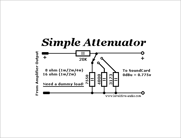
Attenuator circuit diagram
The scheme uses graphical designations of the principles of authorship of Sergey Komarov. I recommend to download [5] and use.
Construction and details
We will need banana connectors (2pcs.) (Or other connectors compatible with your amplifier), one RCA connector, a rotary switch and a knob for it (1/4 "), as well as resistors (see denominations in the scheme).
As a case, I had to buy a plastic case in Chip and Dipe for a frenzy of 90 rubles. But he was very fit in size (65x45x22mm).
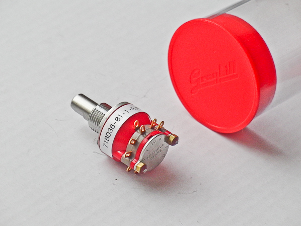
Choosing a rotary switch is a matter of taste. You can choose the cheapest Chinese, and you can - quality. I chose the 2nd option and ordered an expensive Grayhill 71BD36-01-1-AJN. The resource is 50,000 turns, the rotor's contacts are gold-plated (30 microinches is a curious unit of thickness of the coating ), "military acceptance", real American production. I never agitate, but I cite a link to datasheet [4] .
The switch has 10 positions, but we only need three.
Ideally, you still need a minimum of tools: a ruler or a caliper, a drill, a polyhedron key (to fasten the handle to the shaft).
Earthen tire is better to make of copper monozhily. I didn’t have a suitable diameter at hand, and I twisted it from copper conductor (22AWG) and tinned it with lead-free silver-containing solder.
Resistors can take any, 1-2 watts. Ideal to choose wire or foil - they have minimal noise. I chose non-inductive wire mills.
Soldering to the contacts is very convenient - they have a big step, and the switch body is made of thermoplastic and you can be safe from damaging it with a hot soldering iron tip.
After fixing the connectors and soldering the resistors, you can close the case with a cover (I fixed all the parts in the case half), tighten the switch nut, put two screws (attached to the case), fix the handle on the shaft and sign the input voltages on the case.
The finish! You can begin to measure, but this is a topic for a separate article.
useful links
[1] “What do we measure?” (Archive of “Sound producer” magazine)
[2] "Measurement of the output power of audio amplifiers" (Training from Radiookot)
[3] Parallel connection of resistors (resistor page on Wikipedia)
[4] Datashit on Grayhill 71st series
[5] “Good old graphics of schematic diagrams” (author Sergey Komarov)
Source: https://habr.com/ru/post/138448/
All Articles