Introducing the TCP stack for Microchip microcontrollers
Suppose we have a need to create a device with the ability to connect to an Ethernet network. There are quite a few options, but all of them can be divided into 3 types.
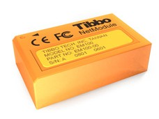
• RS-232 Converter — Ethernet, usually a virtual COM port that converts RS-232 data flow into IP packets at one end, and some device that receives and decodes these packets, and gives it to the controller as RS-232 at the other end. An example of such a device: Tibbo EM100. The merits of such a solution are ease of programming. No need to delve into the intricacies of the protocols, the connected device may not even be aware that the data comes not directly from the serial port, but, for example, from the Internet. There are also disadvantages to this solution — it will not be possible to use higher level protocols such as SNMP, HTTP, and others, i.e. About the WEB-interface, for example, you can forget.
')
• A certain advanced device, a “black box”, which has its own processor, memory, protocol stack, itself handles Ethernet packets, and again gives out RS-232 or SPI to the outside. Examples of such solutions: Lantronix XPort, which is a complete ultra-compact embedded server with a size slightly larger than the RG-45 connector:

chip WIZNET W5100, and Arduino Ethernet Shield based on it:
Here the developer has more freedom, for example, you can raise a WEB-server or Telnet on this controller and control the embedded device through them. Among the shortcomings, it is possible to note the low flexibility (only those protocols that developers have laid down can be used) and the high cost, often exceeding the cost of the controlled device.
• Take control by connecting a physical-level driver (PHY) to your favorite controller, such as an ENC28J60 microcircuit of 10 Base-T standard, or an ENC624J600 microcircuit of 10/100 Base-T standard from the same Microchip company, or PIC18FXXJXX family controller with built-in PHY, and programmatically implement all the necessary protocols. You can write the protocol stack yourself (not a too trivial task), or use the ready-made stack (there is a rather large selection of TCP stacks for microcontrollers from different manufacturers of different degrees of gratuity and quality). This article will provide a brief overview of the Microchip TCP stack, designed for use on microcontrollers of this company.
So, the path is clear, time to decide on the tools.
• One of the stack supported controllers. If we use an external microcircuit PHY, then practically any Microchip production MK, PIC18 (8bit), PIC24 (16bit), and PIC32 (32bit) families. If we want to do without an external PHY, we take something from the PIC18F67J60 family.
• TCP / IP stack Microchip. Stack is part of Microchip Application Libraries (hereinafter referred to as MAL). The library is free, supports a fairly wide range of Microchip controllers, and in addition to the TCP stack also contains a USB stack, a library for working with touchscreens, smart cards, etc. The latest version of the library can be found here .
•Development environment. Free MPLab 8 (slightly outdated, but proven over the years), or MPLab-X (released from Beta-stage a couple of months ago, based on Netbeans, a promising, but not yet very stable development environment).
•Compiler. C18, C30, and C32 are officially supported. The trial 60-day version can be downloaded from the site . After 60 days, the trial version remains functional, but turns off the optimization mode, and therefore the code may require more space in the ROM.
• Programmer and / or in-circuit debugger. I recommend ICD3 or PICKIT3 (ICD2 also works, but is not supported by Mplab-X, and slower).
Instead of soldering your board, you can use one of Microchip’s numerous debugging kits (which are all good, except for their price and the difficulty of buying in Russia):
There are also alternative solutions from Olimex (ENC28J60-H) and Triton (TRT-Ethernet).
Can be operated as a controller with integrated PHY (PIC18F87J60)

or a controller with an external PHY (ENC28J60) connected via the SPI bus (for example, ENC28J60):
From the external strapping, you only need a transformer (for example, PULSE H1012), an RJ-45 connector (there are RJ-45 connectors with an integrated transformer and LEDs at once), and a dozen resistors. To clock the controller, quartz at 25 MHz is required (in this case, the internal frequency of the MK can be raised to 40 MHz using a PLL).
Please note that the external PHY controller ENC624J600 already contains a stitched MAC address, whereas the ENC28J60 and PIC18F87J60 do not have it, and you need to either use the purchased chip containing the MAC or install it programmatically.
Also at this stage it is necessary to decide where the files for the WEB server and SNMP mibs will be stored. There are several options: either directly in the memory of the controller's programs (and with an average stack size with a set of required modules ~ 33kb and a controller with an internal 128kb ROM, we will get ~ 95kb space for files), or use an external EEPROM chip (stack supports 25LC1024), FLASH (series SST25), an SD card or even a USB disk (you will need a PIC32 with USB on board).
So, with the "iron" decided, let's see now, what can this library offer us?
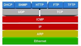
• Protocols: ARP, IP, ICMP, UDP, TCP, DHCP, SNMP, SMTP, HTTP, FTP, TFTP
• TCP and UDP support
• SSL support
• NetBIOS support
• DNS support
There are http-server sources that support GET and POST requests, SSL authentication and GZIP compression, ICMP client and server, SNMP client and server (versions 1, 2 and 3, including SNMP TRAP), TCP2UART software bridge, server TELNET, DynDNS client, DNS, DHCP, and more.
With all this, the stack does not take up so much memory. So, a real project containing a WEB-server, DHCP and DNS-client, Ethernet –Serial bridge, TFTP and SNMP server, SMTP client, will require about 33 kilobytes of program memory (ROM) and 2 kilobytes of data memory (RAM), while that the typical memory size of the PIC18F67J60 is 128kb.
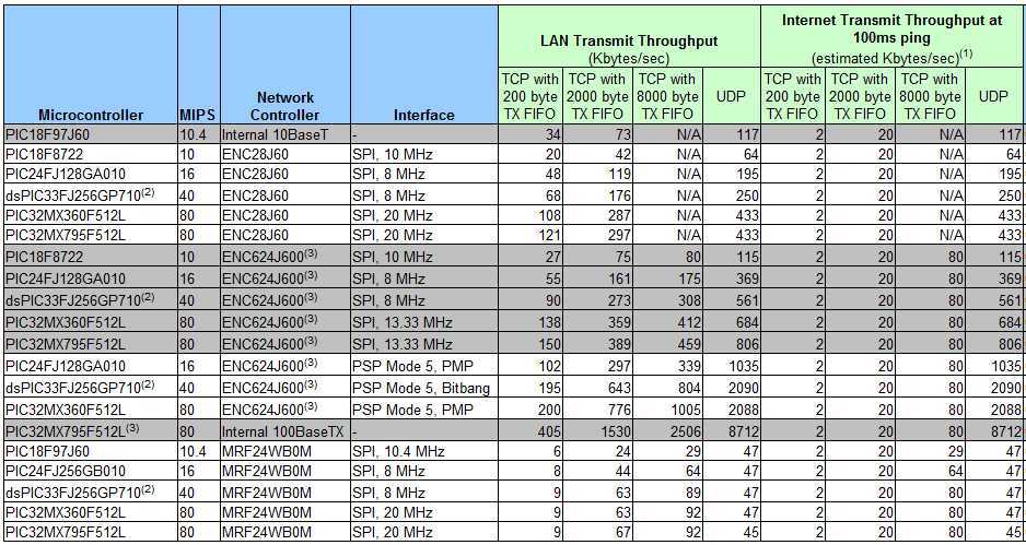
As you can see, the speeds do not amaze the imagination, but do not forget that it is unlikely that anyone will host on such a Facebook device. And a 30kb page with AJAX and a couple of small images will load in less than a second (on the local network).
The MAL distribution contains a number of examples, the most interesting of which are:
• TCPIP Internet Bootloader App - an example that implements a controller firmware update via TFTP.
• TCPIP Internet Radio App-play mp3 stream from the specified site (using an external mp3 decoder chip).
• TCPIP WebVend App - a vending machine emulator with a web interface (GET \ POST, Ajax requests are demonstrated)
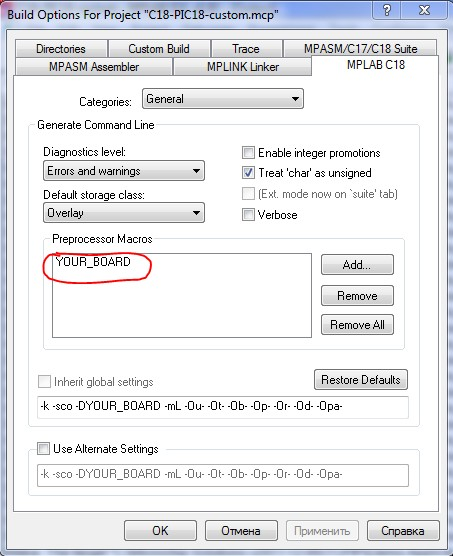
All this is interesting, but it's time to build your own application. Let this be an example of the “Demo App” (from the Microchip Solutions v2011-12-05 \ TCPIP \ Demo App catalog). Go to this folder, and see a bunch of "sishnyh" files, mixed with project files from MPLAB (* .mcp, * .mcw). We are looking for a project file suitable for our debug board. Say, if we have a board called the “Ethernet Starter Kit”, open the C32-PIC32_ETH_SK_ETH795 project. If the board is custom, you can create a project from scratch, or open the most similar project and modify it for yourself. For example, if the board comes with a PIC18F67J60 with a built-in PHY, we take the project C18-PICDN2_ETH97, and refine the file. The revision is as follows: We climb in Project-> Build options-> Project-> C18, and change C18-PICDN2_ETH97 to “YOUR_BOARD”:
Create a file HWP YOUR_BOARD.h based on the most similar. This file contains port numbers for modules using any peripherals. Let's say the SPI_EEPROM.c module takes from there the names of SPI ports for data exchange with an external EEPROM:
If in our user plan the ports are different, we eliminate the discrepancy.
Such excessive complexity of the demonstration projects is connected with the desire of the manufacturer to make it possible so that the example can be run on the maximum possible number of various “hardware”. In the future, when writing your project “from scratch”, all this can be cleaned up and get a simple and understandable structure.
The second interesting file is TCPConfig.h, which, depending on the type of debug card selected, calls the file with the IP protocol parameters. For a user card with PIC18F87J60, this file will be called TCPIP ETH97.h
It enables and disables various stack modules.
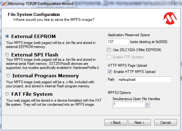
Adjusts the size of buffers, and more. You can also not edit this file manually, but use the wizard that comes with the stack:
So, we will assume that the TCP ports and parameters are configured, the IP address is set, we start compilation. If everything went well, we get the firmware and sew it in the MK, debugger or programmer. We start, check the ping for the address specified in the TCPIP ETH97.h file. If there is no ping, check if the Link LED is on, if the board has not received a different ip-address via DHCP. To check, you can turn off the automatic ip-address receiving mode by
Naturally, we have not uploaded any files to our WEB server yet. We correct this defect. For this we need the utility "Microchip MPFS generator".

The utility converts the specified folder with files to an image file suitable for uploading to an embedded server. As the Source Directory, it must specify the directory with the files to download. The format depends on where we are going to store these files. If we have specified the internal ROM controller as a place to store files, specify the format of C18 / C32 Image, and we get the output file MPFSImg2.c, inside which a large array of binary data will be declared. This file must be added to the project, and recompiled.
If an external FLASH or EEPROM chip is used to store files, select the BIN Image format. The resulting MPFSImg2.bin file is loaded either via the server upload form or by including the appropriate option in the MPFS generator. Download, update the page, enjoy!
Static text is output directly in the HTML file.
To display a dynamic variable on the server’s web page, it is enough to enclose it with tildes, in the form of ~ variable ~, and in the code of the CustomHTPPApp.c file, create a function of the form HTTPPrint_variable ()

Variables in Ajax are created in a similar way, only a dynamic variable is created in a separate XML file, in the form:
~ var1 ~, and in the HTML code of the page, the update function is called: document.getElementById ('var1'). innerHTML = getXMLValue (xmlData, 'var1');
The stack does not use any OS, and works on the principle of cooperative multitasking (however, if you wish, you can also tie the OS, see AN1264). It looks like this:
In main (), an infinite loop rotates, from which functions are called that serve the stack (StackTask and StackApplications) and user functions (in this example, it is user_task (), but there can be anything).
At the same time, you should try to prevent the user function from being executed for too long. For example, if a “dumb” delay of the form while (delay); then the stack functions will not be able to process incoming Ethernet packets, and during this delay communication with the device will disappear. To organize the various timeouts required for normal operation of the IP protocol, the stack uses the hardware timer MK (timer0 or timer1), which operates on an interrupt (the timer function is called TickUpdate).
In addition to implementing the WEB interface and sending SNMP traps, it is quite convenient to use Telnet to output debug information instead of the traditional RS-232 port in such cases.
The subject of Ethernet is very extensive, and in one article it is impossible to tell about everything. For those interested, I suggest to familiarize themselves with the site Microchip Ethernet Design Center , article
Budget Serial to Ethernet adapter in one evening
as well as a series of articles Connecting the microcontroller to the local network
upd: perezalil pictures from the deceased imageshack
• RS-232 Converter — Ethernet, usually a virtual COM port that converts RS-232 data flow into IP packets at one end, and some device that receives and decodes these packets, and gives it to the controller as RS-232 at the other end. An example of such a device: Tibbo EM100. The merits of such a solution are ease of programming. No need to delve into the intricacies of the protocols, the connected device may not even be aware that the data comes not directly from the serial port, but, for example, from the Internet. There are also disadvantages to this solution — it will not be possible to use higher level protocols such as SNMP, HTTP, and others, i.e. About the WEB-interface, for example, you can forget.
')
• A certain advanced device, a “black box”, which has its own processor, memory, protocol stack, itself handles Ethernet packets, and again gives out RS-232 or SPI to the outside. Examples of such solutions: Lantronix XPort, which is a complete ultra-compact embedded server with a size slightly larger than the RG-45 connector:
chip WIZNET W5100, and Arduino Ethernet Shield based on it:
Here the developer has more freedom, for example, you can raise a WEB-server or Telnet on this controller and control the embedded device through them. Among the shortcomings, it is possible to note the low flexibility (only those protocols that developers have laid down can be used) and the high cost, often exceeding the cost of the controlled device.
• Take control by connecting a physical-level driver (PHY) to your favorite controller, such as an ENC28J60 microcircuit of 10 Base-T standard, or an ENC624J600 microcircuit of 10/100 Base-T standard from the same Microchip company, or PIC18FXXJXX family controller with built-in PHY, and programmatically implement all the necessary protocols. You can write the protocol stack yourself (not a too trivial task), or use the ready-made stack (there is a rather large selection of TCP stacks for microcontrollers from different manufacturers of different degrees of gratuity and quality). This article will provide a brief overview of the Microchip TCP stack, designed for use on microcontrollers of this company.
So, the path is clear, time to decide on the tools.
We will need:
• One of the stack supported controllers. If we use an external microcircuit PHY, then practically any Microchip production MK, PIC18 (8bit), PIC24 (16bit), and PIC32 (32bit) families. If we want to do without an external PHY, we take something from the PIC18F67J60 family.
• TCP / IP stack Microchip. Stack is part of Microchip Application Libraries (hereinafter referred to as MAL). The library is free, supports a fairly wide range of Microchip controllers, and in addition to the TCP stack also contains a USB stack, a library for working with touchscreens, smart cards, etc. The latest version of the library can be found here .
•Development environment. Free MPLab 8 (slightly outdated, but proven over the years), or MPLab-X (released from Beta-stage a couple of months ago, based on Netbeans, a promising, but not yet very stable development environment).
•Compiler. C18, C30, and C32 are officially supported. The trial 60-day version can be downloaded from the site . After 60 days, the trial version remains functional, but turns off the optimization mode, and therefore the code may require more space in the ROM.
• Programmer and / or in-circuit debugger. I recommend ICD3 or PICKIT3 (ICD2 also works, but is not supported by Mplab-X, and slower).
Instead of soldering your board, you can use one of Microchip’s numerous debugging kits (which are all good, except for their price and the difficulty of buying in Russia):
- PIC18 Explorer with daughter card PICTail
- Explorer 16 with daughterboard PICTail +
- PIC32 Starter Kit with an IO Expansion Board and PICTail + expansion card (in this case, you will not need an external debugger, because it is already built into the PIC32 Starter Kit)
There are also alternative solutions from Olimex (ENC28J60-H) and Triton (TRT-Ethernet).
If we decide to immediately make our fee:
Can be operated as a controller with integrated PHY (PIC18F87J60)
or a controller with an external PHY (ENC28J60) connected via the SPI bus (for example, ENC28J60):
From the external strapping, you only need a transformer (for example, PULSE H1012), an RJ-45 connector (there are RJ-45 connectors with an integrated transformer and LEDs at once), and a dozen resistors. To clock the controller, quartz at 25 MHz is required (in this case, the internal frequency of the MK can be raised to 40 MHz using a PLL).
Please note that the external PHY controller ENC624J600 already contains a stitched MAC address, whereas the ENC28J60 and PIC18F87J60 do not have it, and you need to either use the purchased chip containing the MAC or install it programmatically.
Also at this stage it is necessary to decide where the files for the WEB server and SNMP mibs will be stored. There are several options: either directly in the memory of the controller's programs (and with an average stack size with a set of required modules ~ 33kb and a controller with an internal 128kb ROM, we will get ~ 95kb space for files), or use an external EEPROM chip (stack supports 25LC1024), FLASH (series SST25), an SD card or even a USB disk (you will need a PIC32 with USB on board).
So, with the "iron" decided, let's see now, what can this library offer us?
Supported functionality:
• Protocols: ARP, IP, ICMP, UDP, TCP, DHCP, SNMP, SMTP, HTTP, FTP, TFTP
• TCP and UDP support
• SSL support
• NetBIOS support
• DNS support
Stack of supported protocols:
There are http-server sources that support GET and POST requests, SSL authentication and GZIP compression, ICMP client and server, SNMP client and server (versions 1, 2 and 3, including SNMP TRAP), TCP2UART software bridge, server TELNET, DynDNS client, DNS, DHCP, and more.
With all this, the stack does not take up so much memory. So, a real project containing a WEB-server, DHCP and DNS-client, Ethernet –Serial bridge, TFTP and SNMP server, SMTP client, will require about 33 kilobytes of program memory (ROM) and 2 kilobytes of data memory (RAM), while that the typical memory size of the PIC18F67J60 is 128kb.
Stack performance:
As you can see, the speeds do not amaze the imagination, but do not forget that it is unlikely that anyone will host on such a Facebook device. And a 30kb page with AJAX and a couple of small images will load in less than a second (on the local network).
The MAL distribution contains a number of examples, the most interesting of which are:
• TCPIP Internet Bootloader App - an example that implements a controller firmware update via TFTP.
• TCPIP Internet Radio App-play mp3 stream from the specified site (using an external mp3 decoder chip).
• TCPIP WebVend App - a vending machine emulator with a web interface (GET \ POST, Ajax requests are demonstrated)
We collect the project
All this is interesting, but it's time to build your own application. Let this be an example of the “Demo App” (from the Microchip Solutions v2011-12-05 \ TCPIP \ Demo App catalog). Go to this folder, and see a bunch of "sishnyh" files, mixed with project files from MPLAB (* .mcp, * .mcw). We are looking for a project file suitable for our debug board. Say, if we have a board called the “Ethernet Starter Kit”, open the C32-PIC32_ETH_SK_ETH795 project. If the board is custom, you can create a project from scratch, or open the most similar project and modify it for yourself. For example, if the board comes with a PIC18F67J60 with a built-in PHY, we take the project C18-PICDN2_ETH97, and refine the file. The revision is as follows: We climb in Project-> Build options-> Project-> C18, and change C18-PICDN2_ETH97 to “YOUR_BOARD”:
Create a file HWP YOUR_BOARD.h based on the most similar. This file contains port numbers for modules using any peripherals. Let's say the SPI_EEPROM.c module takes from there the names of SPI ports for data exchange with an external EEPROM:
#define EEPROM_CS_TRIS (TRISCbits.TRISC0)
#define EEPROM_CS_IO (LATCbits.LATC0)
#define EEPROM_SCK_TRIS (TRISCbits.TRISC3)
#define EEPROM_SDI_TRIS (TRISCbits.TRISC4)
#define EEPROM_SDO_TRIS (TRISCbits.TRISC5)
If in our user plan the ports are different, we eliminate the discrepancy.
Such excessive complexity of the demonstration projects is connected with the desire of the manufacturer to make it possible so that the example can be run on the maximum possible number of various “hardware”. In the future, when writing your project “from scratch”, all this can be cleaned up and get a simple and understandable structure.
The second interesting file is TCPConfig.h, which, depending on the type of debug card selected, calls the file with the IP protocol parameters. For a user card with PIC18F87J60, this file will be called TCPIP ETH97.h
It enables and disables various stack modules.
/* Application Level Module Selection
* Uncomment or comment the following lines to enable or
* disabled the following high-level application modules.
*/

#define STACK_USE_UART // Application demo using UART for IP address display and stack configuration
#define STACK_USE_UART2TCP_BRIDGE // UART to TCP Bridge application example
//#define STACK_USE_IP_GLEANING

:
#define MPFS_USE_EEPROM
//#define MPFS_USE_SPI_FLASH

IP- :
#define MY_DEFAULT_IP_ADDR_BYTE1
Adjusts the size of buffers, and more. You can also not edit this file manually, but use the wizard that comes with the stack:
So, we will assume that the TCP ports and parameters are configured, the IP address is set, we start compilation. If everything went well, we get the firmware and sew it in the MK, debugger or programmer. We start, check the ping for the address specified in the TCPIP ETH97.h file. If there is no ping, check if the Link LED is on, if the board has not received a different ip-address via DHCP. To check, you can turn off the automatic ip-address receiving mode by
#define STACK_USE_DHCP_CLIENT out the lines #define STACK_USE_DHCP_CLIENT and #define STACK_USE_IP_GLEANING . Having finally received the ping, we try to enter the address of the board in the browser. We see an error 404, page not found.Naturally, we have not uploaded any files to our WEB server yet. We correct this defect. For this we need the utility "Microchip MPFS generator".
The utility converts the specified folder with files to an image file suitable for uploading to an embedded server. As the Source Directory, it must specify the directory with the files to download. The format depends on where we are going to store these files. If we have specified the internal ROM controller as a place to store files, specify the format of C18 / C32 Image, and we get the output file MPFSImg2.c, inside which a large array of binary data will be declared. This file must be added to the project, and recompiled.
If an external FLASH or EEPROM chip is used to store files, select the BIN Image format. The resulting MPFSImg2.bin file is loaded either via the server upload form or by including the appropriate option in the MPFS generator. Download, update the page, enjoy!
A couple of words about how it works
Static text is output directly in the HTML file.
To display a dynamic variable on the server’s web page, it is enough to enclose it with tildes, in the form of ~ variable ~, and in the code of the CustomHTPPApp.c file, create a function of the form HTTPPrint_variable ()
Variables in Ajax are created in a similar way, only a dynamic variable is created in a separate XML file, in the form:
~ var1 ~, and in the HTML code of the page, the update function is called: document.getElementById ('var1'). innerHTML = getXMLValue (xmlData, 'var1');
The stack does not use any OS, and works on the principle of cooperative multitasking (however, if you wish, you can also tie the OS, see AN1264). It looks like this:
In main (), an infinite loop rotates, from which functions are called that serve the stack (StackTask and StackApplications) and user functions (in this example, it is user_task (), but there can be anything).
do
{
StackTask();
StackApplications();
user_task();
CLRWDT(); //
}while(1);
At the same time, you should try to prevent the user function from being executed for too long. For example, if a “dumb” delay of the form while (delay); then the stack functions will not be able to process incoming Ethernet packets, and during this delay communication with the device will disappear. To organize the various timeouts required for normal operation of the IP protocol, the stack uses the hardware timer MK (timer0 or timer1), which operates on an interrupt (the timer function is called TickUpdate).
In addition to implementing the WEB interface and sending SNMP traps, it is quite convenient to use Telnet to output debug information instead of the traditional RS-232 port in such cases.
Conclusion
The subject of Ethernet is very extensive, and in one article it is impossible to tell about everything. For those interested, I suggest to familiarize themselves with the site Microchip Ethernet Design Center , article
Budget Serial to Ethernet adapter in one evening
as well as a series of articles Connecting the microcontroller to the local network
upd: perezalil pictures from the deceased imageshack
Source: https://habr.com/ru/post/138081/
All Articles