Methods of assembly and disassembly of laptops for repair on the example of Toshiba Portege M800
In this topic, I would like to share my thoughts on the repair and disassembly of laptops, since I have accumulated a small and modest experience. It's about the captured and commented-out build process of the Toshiba Portege M800 laptop. The idea of capturing in the photos came after the laptop was disassembled, so the assembly is represented by pictures. In addition, I hope the article will be useful repairing this device. The main important points found in the topic are gathered together at the end.
Careful traffic (24 photos).
At first, I want to note that any practical use of this article is entirely at your own peril and risk! Remember that it is better to ask or google (and sometimes just think a little longer) than to try to do something you don’t understand.
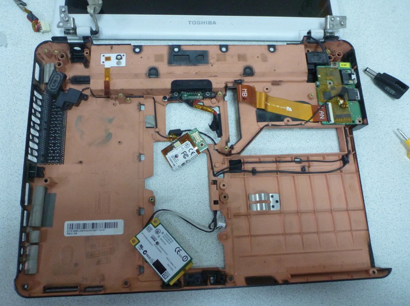
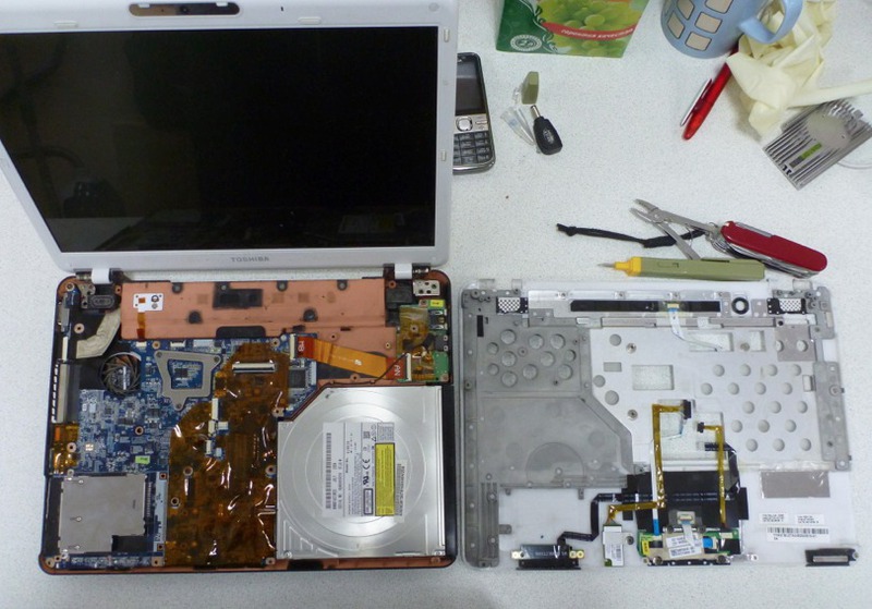
It was necessary to disassemble the laptop in order to search for a place of poor contact in the power circuit. For this, the cable harness with a connector for connecting the adapter to the motherboard was removed (for study, pressing the contacts and, if necessary, soldering in the problem area). It is difficult to name the component, for the sake of extraction which would have to disassemble the laptop in more detail:
')
With this repair, we will need a screwdriver (Phillips screwdriver) (carefully select the size of the screws) and a wooden or plastic planochka, which is not a pity to periodically sharpen to a chisel. A good option is a disposable Chinese chopstick. It will be almost a consumable item.
When disassembling, I recommend using small closable containers for screws with signatures that uniquely allow you to restore their purpose and location during assembly. Closing, because there is a high probability that after disassembling something will distract from the process, and it will be necessary to assemble and pack the disassembled device forbetter assembly times , and not to disperse the cogs throughout the district at some local cataclysm. Anything is right for you. This time there were plastic Eppendorf tubes (eppendorfs) on hand:

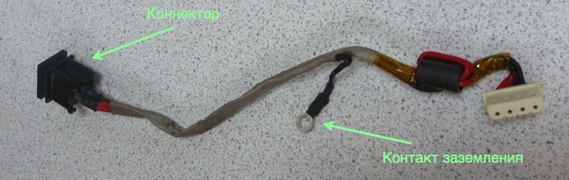
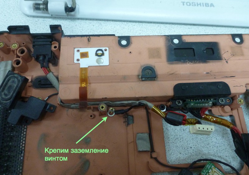
First of all, install the connector in the case and gently run the wiring harness as shown in the photo. Incorrectly insert the connector itself is almost impossible - its form is quite unambiguous. After installation, fasten the grounding with a screw to the case with an orange conductive coating.
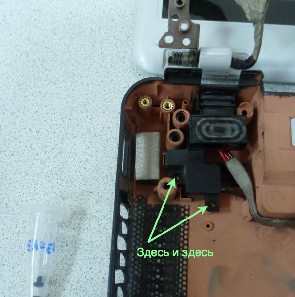
Now we put the left speaker in place and fasten it with two carefully preserved screws.
The screws must be tightened to a reasonable moment. Doing it too hard, “for ages” is not worth it - you can spoil the aesthetics of the screw slot and also deform the plastic. In addition, it will complicate thefollowing possible disassembly.
Go to the right loop of the monitor. Carefully lay the wire of the WiFi antenna deep into the right of the right speaker, put the monitor hinges in place and fix them with the appropriate screws.
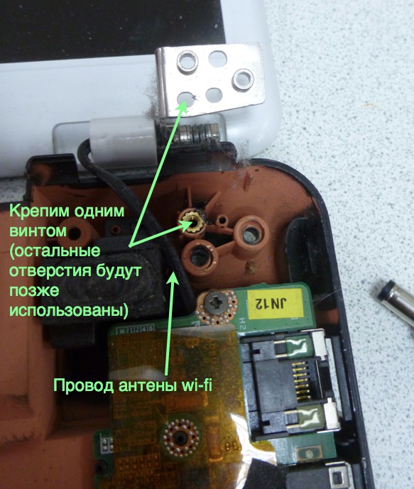
The hinges are usually quite tight, so it is best to bend them both at once and fasten them together, putting the monitor in the most comfortable position.
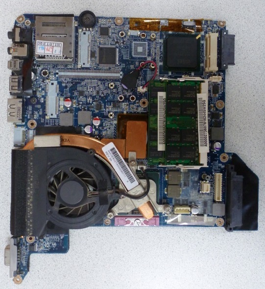
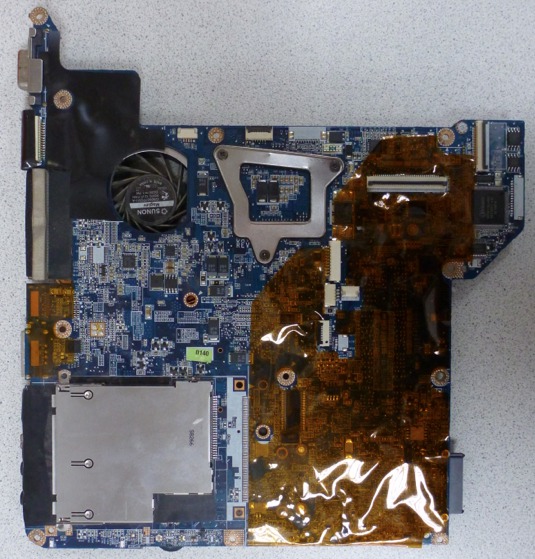
Types of the motherboard below and above, respectively:
When working with printed circuit boards it is extremely important to exercise caution with static electricity. Regularly equalize your potential and the potential of the earth on the board (by touching the metal case of the connector on the side of the board, for example). This is especially true when using woolen clothes and / or concentrated fidgeting on a chair, without which it will be difficult to manage. Ideally, it is good to use an antistatic bracelet.
We install the motherboard on the place it was supposed to (it is also quite difficult to install it incorrectly). Do not forget to be careful when its connectors or other parts rest against the body of the laptop. If excessive force is applied, the contact of these parts with the board can be broken. Not useful to the board and the bending deformation.
Carefully hide the monitor cable deep into the right of the left speaker and connect it to the appropriate connector. The arrows indicate where to connect the cable:
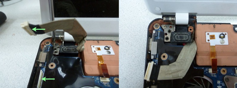
We work very carefully and “sensually” with the fastening of the plugs of the cables and just the wires. While smoothly holding both parts, slowly apply the insertion force until you feel the characteristic soft snap. Depending on the connector, it can be very soft and not very clicking, but it is quite possible to feel it, in my opinion. There is no need to exert more force, it can damage the soldering of the connector or something even worse.
Disconnect the cables conveniently with our homemade wooden chisel. Her form is a tribute to your ingenuity and love of comfort. Usually it is convenient that it is about 5-10 mm wide with a sharp enough sharpening so that it can be inserted into a narrow slot. Also, a wooden stick will not close the contacts when you accidentally touch the board.
The screws to be installed in the next step are shown with red arrows. Next we connect the loops of the Power button with the LED, as well as the network card to the motherboard:
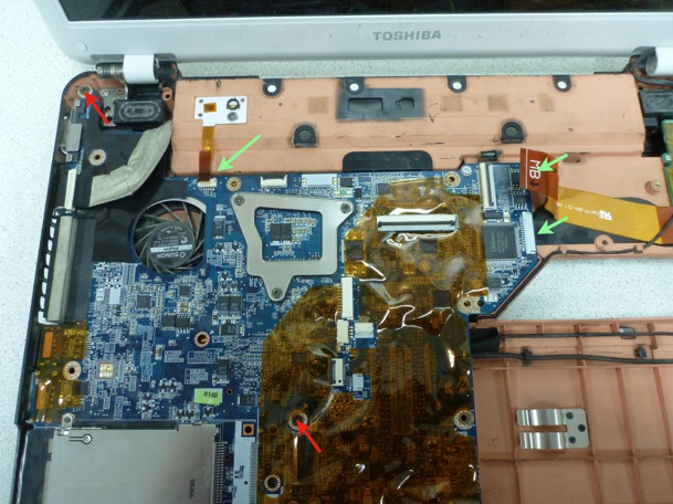
These two cables do not have a plastic connector at the end; instead, there is a pull-tab for easy removal. The tongue and cable, pressed together, form a rigid enough structure to gently insert into the connector on the motherboard. With a sufficiently slow and neat application of force, you can feel that the train has entered to the end. You can evaluate this by attaching the end of the cable to the connector before inserting it and estimating the length to which it should enter. Also, with a certain skill, you can carefully try to use only the tongue in order to insert the end of the plume into place.
When we see when disassembling that there are many holes for the screws, and only some of them are occupied at this stage, it is better not to be lazy and at least write or sketch, and it is better to sfotkat this moment. Recall such things can be difficult. For example, in the photo above you can see that of all the holes at this stage, screws require only two. The remaining holes imply end-to-end use with the top and / or bottom cover.
Now it's time to connect expansion cards on the other side of the motherboard. Do not forget to connect the connectors of power wires, battery boards and wi-fi antennas going to the monitor.
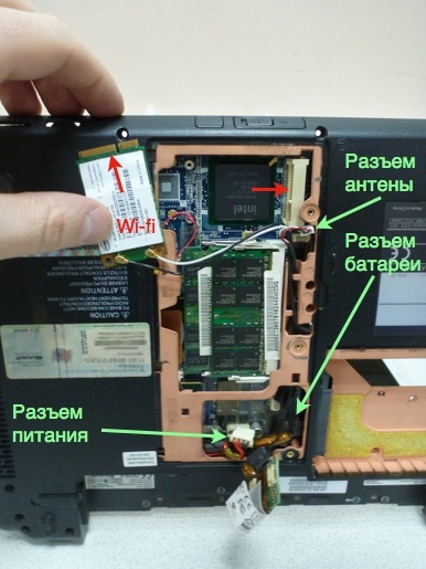
We insert the Wi-Fi card in its place in the mini PCI-E slot. We monitor before this the cleanliness of contacts. Do not touch the metal contact plates with your fingers. The card is fixed with two screws.
Do the same with the modem. Its connector is vertical. Gently press it down until it has a smooth click. This is best done slowly to feel that the connector is fully in place. Also fix the corresponding screw from our “cash”:

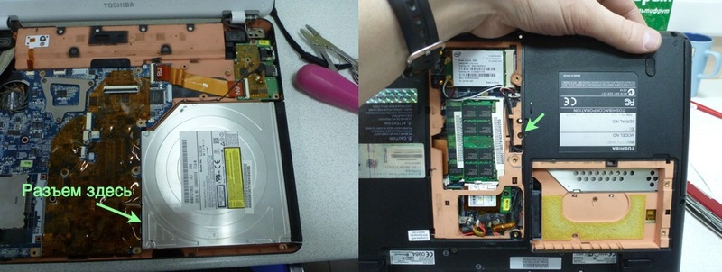
Now we put in place the optical drive. Its form also leaves no doubt about the correctness / incorrectness of the setting in place. We insert the connector in the same way as we did with the network card, without touching the contacts. Drive into the slot should be pushed from right to left when looking at an open laptop in a natural way. Fasten it with a screw from the back cover.
The next stage of the assembly will be the connection and fastening of the top cover:
I would like to immediately note that the operation of removing this cover, in my opinion, is the most potentially dangerous for both damage and damage to the appearance of the device. When disassembling, remember two things.
Firstly, after you have unscrewed all imaginable and inconceivable screws that hold the lid in your opinion, you need to find where the plastic latches are located, which can (and most likely will) hold it in addition to the screws. There may be two failures here - either inaccurately prying the lid with something solid and flat, leaving unpleasant signs of “opening” the patient in the docking areas of the lower and upper lids, or the latch can be broken off, which can lead to a loose joint. cracks are formed. Therefore, I recommend using a flat tool made of a material that is obviously softer than the material of the caps for prying. This may be a disposable Chinese chopstick, cut with a knife from the wide end to the chisel condition, or a similar piece of soft plastic. I advise you to do such a “tool” manually, because, because of the softness, it lasts for a while, after which you need to regain it. However, this is a fee for the aesthetic pleasure of the joint in the body after assembly (if such was originally the place to be). After one side of the lid is left, which only holds on the latches, it is useful to shake the lid up and down, thereby gently releasing it from their grip. At this moment, the main thing is not to hurry, because it is one of the most “traumatic” for the product to be repaired.
Secondly - from the cover to the motherboard, as a rule, there are loops, the connectors of which can be located approximately in the center of the motherboard. It’s pretty easy to damage them in many different parts. Therefore, after the cover has succumbed, carefully look under it, find out what and how it is connected to the motherboard, in order to carefully disconnect, not bringing the cables to critical deformation when lifting the cover.
In this case, the cables to the motherboard are quite accessible without lifting the cover.
By the way, Toshiba carefully indicated the marking of screws for convenience. The presence of such a marking (F number ) for an empty thread also indicates that the screw must be tightened on this layer of the assembly.

Among the fastening loops there are connectors with a folding clamping plastic plate:
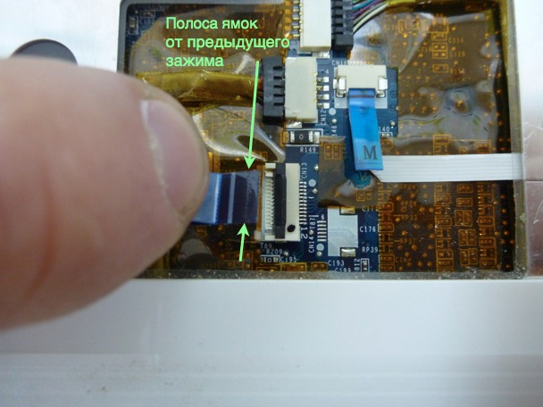
Fold it to install, set the end of the cable clearly in a shallow recess for it (fix in the transverse direction), and then stick in about the dimples on the cable from the previous clip. Close the plan. Correctly clamped train should stick tightly enough. If it is removed, then you need once again carefully and correctly position the cable in the recess for it and deepen into the connector to the end before snapping into place. Patience and accuracy when connecting loops will pay off when you do not need to disassemble a fully assembled device, because some equipment on board will not work (in this case, the touchpad or light bulbs on the case, or buttons for the player above the keyboard, for example).
It is convenient to put the keyboard, having thrown off on itself. Then the cable will be easy to connect. Its connector is also provided with a flip bar:
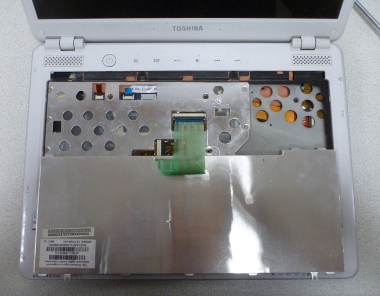
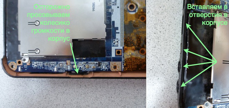
The keyboard is often attached with latches on the sides. In our case, they are below and above (the lower ones are marked with arrows). There are still two screws on top (above the inter-buttons F1-F2 and END-INS). The space above the clave is closed by a white plastic planochka that just snaps into place.

After clicking the plastic plank above the keyboard, the top of the case is ready.
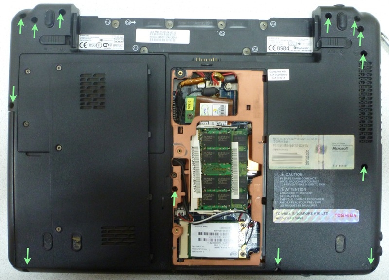
Now back to the bottom cover. Install the screws as in the photo:

Put the hard drive in place. As always, carefully and gently (and most importantly - to the end) combine the connectors. Screws fixing the body of the disk to screw until it is necessary.
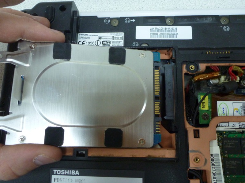
The queue of the remaining screws back cover. The screws of the hard disk compartment cover are fixed in the body of the laptop and the disk itself. Finally, close and tighten the three screws of the central memory compartment, modem and network card.
It remains to install the batteryto remove the bandages and check the performance!
After everything has been successfully loaded and there will be no visible problems, it’s good to get into the device manager in Windows or in lspci and others like it in Linux or in the system information in Mac to make sure that the peripherals are successfully recognized and working. After successfully passing the test, you can finally exhale, relax and enjoy the integrity of the device, which has just beenevenly distributed on the table and boxes, and now breathes life.
Successes!
Careful traffic (24 photos).
At first, I want to note that any practical use of this article is entirely at your own peril and risk! Remember that it is better to ask or google (and sometimes just think a little longer) than to try to do something you don’t understand.
It was necessary to disassemble the laptop in order to search for a place of poor contact in the power circuit. For this, the cable harness with a connector for connecting the adapter to the motherboard was removed (for study, pressing the contacts and, if necessary, soldering in the problem area). It is difficult to name the component, for the sake of extraction which would have to disassemble the laptop in more detail:
')
With this repair, we will need a screwdriver (Phillips screwdriver) (carefully select the size of the screws) and a wooden or plastic planochka, which is not a pity to periodically sharpen to a chisel. A good option is a disposable Chinese chopstick. It will be almost a consumable item.
When disassembling, I recommend using small closable containers for screws with signatures that uniquely allow you to restore their purpose and location during assembly. Closing, because there is a high probability that after disassembling something will distract from the process, and it will be necessary to assemble and pack the disassembled device for
First of all, install the connector in the case and gently run the wiring harness as shown in the photo. Incorrectly insert the connector itself is almost impossible - its form is quite unambiguous. After installation, fasten the grounding with a screw to the case with an orange conductive coating.
Now we put the left speaker in place and fasten it with two carefully preserved screws.
The screws must be tightened to a reasonable moment. Doing it too hard, “for ages” is not worth it - you can spoil the aesthetics of the screw slot and also deform the plastic. In addition, it will complicate the
Go to the right loop of the monitor. Carefully lay the wire of the WiFi antenna deep into the right of the right speaker, put the monitor hinges in place and fix them with the appropriate screws.
The hinges are usually quite tight, so it is best to bend them both at once and fasten them together, putting the monitor in the most comfortable position.
Types of the motherboard below and above, respectively:
When working with printed circuit boards it is extremely important to exercise caution with static electricity. Regularly equalize your potential and the potential of the earth on the board (by touching the metal case of the connector on the side of the board, for example). This is especially true when using woolen clothes and / or concentrated fidgeting on a chair, without which it will be difficult to manage. Ideally, it is good to use an antistatic bracelet.
We install the motherboard on the place it was supposed to (it is also quite difficult to install it incorrectly). Do not forget to be careful when its connectors or other parts rest against the body of the laptop. If excessive force is applied, the contact of these parts with the board can be broken. Not useful to the board and the bending deformation.
Carefully hide the monitor cable deep into the right of the left speaker and connect it to the appropriate connector. The arrows indicate where to connect the cable:
We work very carefully and “sensually” with the fastening of the plugs of the cables and just the wires. While smoothly holding both parts, slowly apply the insertion force until you feel the characteristic soft snap. Depending on the connector, it can be very soft and not very clicking, but it is quite possible to feel it, in my opinion. There is no need to exert more force, it can damage the soldering of the connector or something even worse.
Disconnect the cables conveniently with our homemade wooden chisel. Her form is a tribute to your ingenuity and love of comfort. Usually it is convenient that it is about 5-10 mm wide with a sharp enough sharpening so that it can be inserted into a narrow slot. Also, a wooden stick will not close the contacts when you accidentally touch the board.
The screws to be installed in the next step are shown with red arrows. Next we connect the loops of the Power button with the LED, as well as the network card to the motherboard:
These two cables do not have a plastic connector at the end; instead, there is a pull-tab for easy removal. The tongue and cable, pressed together, form a rigid enough structure to gently insert into the connector on the motherboard. With a sufficiently slow and neat application of force, you can feel that the train has entered to the end. You can evaluate this by attaching the end of the cable to the connector before inserting it and estimating the length to which it should enter. Also, with a certain skill, you can carefully try to use only the tongue in order to insert the end of the plume into place.
When we see when disassembling that there are many holes for the screws, and only some of them are occupied at this stage, it is better not to be lazy and at least write or sketch, and it is better to sfotkat this moment. Recall such things can be difficult. For example, in the photo above you can see that of all the holes at this stage, screws require only two. The remaining holes imply end-to-end use with the top and / or bottom cover.
Now it's time to connect expansion cards on the other side of the motherboard. Do not forget to connect the connectors of power wires, battery boards and wi-fi antennas going to the monitor.
We insert the Wi-Fi card in its place in the mini PCI-E slot. We monitor before this the cleanliness of contacts. Do not touch the metal contact plates with your fingers. The card is fixed with two screws.
Do the same with the modem. Its connector is vertical. Gently press it down until it has a smooth click. This is best done slowly to feel that the connector is fully in place. Also fix the corresponding screw from our “cash”:
Now we put in place the optical drive. Its form also leaves no doubt about the correctness / incorrectness of the setting in place. We insert the connector in the same way as we did with the network card, without touching the contacts. Drive into the slot should be pushed from right to left when looking at an open laptop in a natural way. Fasten it with a screw from the back cover.
The next stage of the assembly will be the connection and fastening of the top cover:
I would like to immediately note that the operation of removing this cover, in my opinion, is the most potentially dangerous for both damage and damage to the appearance of the device. When disassembling, remember two things.
Firstly, after you have unscrewed all imaginable and inconceivable screws that hold the lid in your opinion, you need to find where the plastic latches are located, which can (and most likely will) hold it in addition to the screws. There may be two failures here - either inaccurately prying the lid with something solid and flat, leaving unpleasant signs of “opening” the patient in the docking areas of the lower and upper lids, or the latch can be broken off, which can lead to a loose joint. cracks are formed. Therefore, I recommend using a flat tool made of a material that is obviously softer than the material of the caps for prying. This may be a disposable Chinese chopstick, cut with a knife from the wide end to the chisel condition, or a similar piece of soft plastic. I advise you to do such a “tool” manually, because, because of the softness, it lasts for a while, after which you need to regain it. However, this is a fee for the aesthetic pleasure of the joint in the body after assembly (if such was originally the place to be). After one side of the lid is left, which only holds on the latches, it is useful to shake the lid up and down, thereby gently releasing it from their grip. At this moment, the main thing is not to hurry, because it is one of the most “traumatic” for the product to be repaired.
Secondly - from the cover to the motherboard, as a rule, there are loops, the connectors of which can be located approximately in the center of the motherboard. It’s pretty easy to damage them in many different parts. Therefore, after the cover has succumbed, carefully look under it, find out what and how it is connected to the motherboard, in order to carefully disconnect, not bringing the cables to critical deformation when lifting the cover.
In this case, the cables to the motherboard are quite accessible without lifting the cover.
By the way, Toshiba carefully indicated the marking of screws for convenience. The presence of such a marking (F number ) for an empty thread also indicates that the screw must be tightened on this layer of the assembly.
Among the fastening loops there are connectors with a folding clamping plastic plate:
Fold it to install, set the end of the cable clearly in a shallow recess for it (fix in the transverse direction), and then stick in about the dimples on the cable from the previous clip. Close the plan. Correctly clamped train should stick tightly enough. If it is removed, then you need once again carefully and correctly position the cable in the recess for it and deepen into the connector to the end before snapping into place. Patience and accuracy when connecting loops will pay off when you do not need to disassemble a fully assembled device, because some equipment on board will not work (in this case, the touchpad or light bulbs on the case, or buttons for the player above the keyboard, for example).
It is convenient to put the keyboard, having thrown off on itself. Then the cable will be easy to connect. Its connector is also provided with a flip bar:
The keyboard is often attached with latches on the sides. In our case, they are below and above (the lower ones are marked with arrows). There are still two screws on top (above the inter-buttons F1-F2 and END-INS). The space above the clave is closed by a white plastic planochka that just snaps into place.
After clicking the plastic plank above the keyboard, the top of the case is ready.
Now back to the bottom cover. Install the screws as in the photo:
Put the hard drive in place. As always, carefully and gently (and most importantly - to the end) combine the connectors. Screws fixing the body of the disk to screw until it is necessary.
The queue of the remaining screws back cover. The screws of the hard disk compartment cover are fixed in the body of the laptop and the disk itself. Finally, close and tighten the three screws of the central memory compartment, modem and network card.
It remains to install the battery
After everything has been successfully loaded and there will be no visible problems, it’s good to get into the device manager in Windows or in lspci and others like it in Linux or in the system information in Mac to make sure that the peripherals are successfully recognized and working. After successfully passing the test, you can finally exhale, relax and enjoy the integrity of the device, which has just been
Summarizing, I will give a set of tips
- If possible, work on a clean, flat surface, without small abrasive particles. Elozenia on the table is inevitable, so the patient's body can be scratched. From a rough surface, small parts will always strive to escape downwards.
- Carefully take care of the screws, pack them in safe containers so that you can quickly pack [the floor] of the disassembled device until better assembly times. The probability of postponing is quite high, and, in my opinion, this is a good habit.
- Carefully document the disassembly process. Best of all, take a picture. If you do not fotkaete, then write, draw. The specificity of the repair is that we return to the assembly, sometimes, much later than planned. Something is distracting or lacking moral strength at the moment - everything should be ready to resume repair in time >> time, when you still remember the order of screwing and the purpose of the screws. Unobtrusive moments, such as a poorly visible disconnected loop, write / mark especially.
- When working with the separation of plastic parts, resist the temptation to use a screwdriver for a flat slot or a knife. Use dielectric (if near electronics) tools that are softer than disconnectable parts. The same applies to the disconnection of thin metal compounds, where it is important to maintain an intact appearance. Panned Chinese disposable chopstick is an excellent candidate.
- Remember about electrostatic danger. Do not touch parts of the boards with metal objects (such as tweezers) and do not hold them close. It is better not to use metal tools other than a screwdriver. Regularly touch the safe, solid metal part of the device, such as the connector body, with a hand and a screwdriver to level the potentials. Or use an antistatic bracelet.
- Be gentle, tender and attentive with connectors. Remember the “science of contacts.” In my opinion, a huge number of problems can be avoided by taking care to connect the connectors.
- Try to understand the purpose of a particular train, to follow where it goes, what connects it. Pay special attention if, in your opinion, something looks illogical. Do not wave your hand at such a moment. This is your chance to upgrade the level of understanding, the ability to understand, and with them the general experience, which is so necessary when solving more complex problems.
- In my opinion, patience, desire and a reasonable approach can work wonders in the repair, even if the experience has not yet accumulated. Do not be afraid to investigate an unknown problem. With a careful and patient approach, you will be able to stop in time, faced with an unknown / insoluble problem and do reversible (accuracy is needed just for this) steps in reverse order, at least where they started from where they started.
Successes!
Source: https://habr.com/ru/post/138016/
All Articles