We communicate with the SIM card at a low level
f: I can’t imagine how a cruiser can work) Our students usually gather somewhere on the shelves
m: Here I have a fee. You need to get a SIM card for it, and this card should read SMS from there)
m: purchase fee, but we program it)
f: can you not read the SMS from the phone?
- from life, spelling preserved
')
Well, if you are still interested to learn more about SIM cards, transfer protocols and their file structure, I ask for cat. Well, where without the code ...
1. Introduction
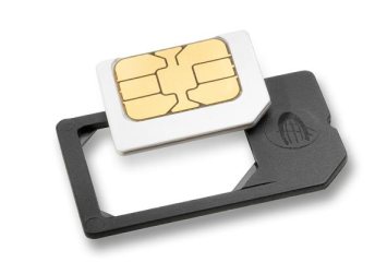
You should start with the fact that the SIM card is a kind of smart card, so it fully complies with the ISO-7816 standard. I will not say what conclusions it has (this was already discussed in detail in the previous article ).
Some SIM cards (more precisely, smart cards) can supply a clock signal up to 20 MHz. But after all, when the SIM card is turned on, the terminal does not know its parameters, therefore, communication begins with a maximum of 4 MHz. Subsequently, the terminal recognizes Simka better and can change the transmission parameters.
A pull-up resistor of 20 KΩ must be connected to the I / O pin. In those moments when the terminal and SIM card have nothing to say to each other (i.e., they are both in the Z-state), this resistor will provide a logical unit at the output.
2. Activation / Deactivation
SIM card activation and subsequent cold reset
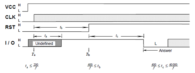
The diagram is quite simple, cold reset starts from the time point T a . It is only necessary to note that I / O is controlled here only by a sim card. The terminal should ignore any signal on it while RST is at zero. After Simka is obliged to give an answer (Answer to reset).
Deactivation
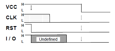
There is no definite time frame, I / O is also controlled by a sim card.
3. Transmission protocols
All smart cards and, accordingly, SIM cards, there are two types of transmission protocols - byte T0 and block T1. I will consider only T0.
At once I will say that T0 is like two peas in a pod like UART (it is used in the transmission on the COM port). But with a few reservations. Let's start from the beginning.
The time in the T0 protocol is called the elementary unit of time (etu), which is equal to:
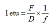
where F (clock conversion rate) and D (bit rate control factor) are set based on the ATR, and f is the clock frequency for the card. By default, F = 372, and D = 1.
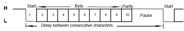
The transfer on the I / O pin begins with the advent of the start bit - the decay from the logical one. The time allotted to each bit is etu. Next come 8 data bits, 1 parity bit and at least 2 stop bits. The time interval between two start bits must always be greater than or equal to 12 etu and less than or equal to 9,600 etu.
4. Answer to reset
As I said, Simka sends an ATR after a cold reset. It contains information with the recommended value of the synchronization frequency, a list of supporting transmission protocols, etc.
The very first byte in ATR is TS. It shows which encoding is applied, direct or inverse.
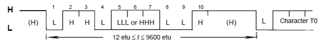
Forward encoding: if TS is HHLH HHLL, then the high voltage level in the I / O circuit encodes a logical unit, and time 2 in the figure encodes the least significant bit . With this encoding, the TS byte value is 0x3B.
Reverse coding: if TS is HHLL LLLL, then the low voltage level in the I / O circuit encodes a logical one, and H is a logical zero. Time 2 in the figure encodes the most significant bit . With this encoding, the TS byte value is 0x3F.
The remaining bytes contain service information, for example, the recommended values of F and D, affecting the value of etu.
5. Command structure
Commands are divided into two types: Command Transport Data Unit (C-TPDU) and Response Transport Data Unit (R-TPDU), i.e. team and the answer to it. Teams always make up a pair: R-TPDU will respond to any command transmitted to the card. R-TPDU always ends with a status byte characterizing the success of a command.
C-TPDU structure:
| Code | Length | Description | |
| CLA | one | Instruction class | Headline |
| INS | one | Instruction code | |
| P1 | one | Parameter instructions 1 | |
| P2 | one | Parameter instructions 2 | |
| Lc | 0 or 1 | The number of bytes in the Data field | |
| Data | Lc | Command data | Body |
| Le | 0 or 1 | Maximum number of bytes expected in response |
Not all cards can immediately take the header and body of the team, in this case, you must first send the header, wait for the response status byte, and then send the body of the command.
It is worth noting that if we make a mistake in any parameter of the command, Simka will report this in the status byte, but she has the right to ignore the command if it was absolutely incorrect (for example, it consisted of one byte).
R-TPDU structure:
| Code | Length | Description |
| Data | Lr | Response data |
| SW1 | one | Status byte 1 |
| SW2 | one | Status byte 2 |
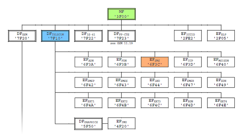
6. File structure
File types:
1. Master file (MF) - root.
2. Dedicated files (DF) - ordinary folders.
3. Elementary files (EF) are divided into:
- Transparent EF - consist of a sequence of bytes,
- Linear fixed EF - consist of a sequence of records of the same size,
- Cyclic EF is the same, but when the end of the file is reached, the next entry starts with a zero entry, in a circle.
7. Examples of commands
Let's try to read and write the SMS message in the EF SMS file in the DF TELECOM folder.
1) SELECT
Before performing a file operation, you must first select it. First you need to select the folder DF TELECOM .
Sending a SELECT command header:
A0 A4 00 00 02
Answer - status byte:
A4 (repeats byte instructions)
Sending command body:
7F 10 (ID of this folder)
Similarly, choose EF SMS .
2) READ RECORD
After we have selected the file containing all the sms, you can try to read one of them.
Sending the READ RECORD command header:
A0 B2 01 04 B0 (01 is the sequence number of SMS)
Answer:
B2 07 07 91 97 62 92 90 90 F0 11 FF 04 81 21 43 00 08 FF 08 04 45 04 30 04 31 04 40 FF FF FF
FF FF FF FF FF FF FF FF FF FF FF FF FF FF FF FF FF FF FF FF FF FF FF FF FF FF FF FF FF FF FF FF FF
FF FF FF FF FF FF FF FF FF FF FF FF FF FF FF FF FF FF FF FF FF FF FF FF FF FF FF FF FF FF FF FF FF
FF FF FF FF FF FF FF FF FF FF FF FF FF FF FF FF FF FF FF FF FF FF FF FF FF FF FF FF FF FF FF FF FF
FF FF FF FF FF FF FF FF FF FF FF FF FF FF FF FF FF FF FF FF FF FF FF FF FF FF FF FF FF FF FF FF FF
FF FF FF FF FF FF FF FF FF FF FF 90 00
All but the first and last two bytes (B2, 07, 90, 00) is a message record. We analyze it.
| 07 | The length of the SMS center number in bytes. |
| 91 | Type of SMS center number (in this case, it is presented in the international format). |
| 97 62 92 90 90 F0 | SMS center number - + 7-926-290-90-90 (read from the end of the byte). The symbol F is needed for alignment. |
| eleven | The length of the SMS center. |
| 04 | The length of the number of the sender. |
| 81 | Type of sender number. |
| 21 43 | The number of the sender is 1234 (again read from the end of the byte). |
| 00 | Protocol identifier |
| 08 | Encoding (00 - only Latin, 08 - with Cyrillic). |
| 08 | The length of the message in bytes. |
| 04 45 04 30 04 31 04 40 | The message is “Habr.” Encoded in UTF-16. |
It is important to note that when the message contains only Latin characters, a special 7-bit GSM encoding is used.
Take the word "hi".
| h | i | |
| 68 | 69 | We look in UTF-8. |
| 0 110 1000 | 0110 100 1 | Convert to binary. |
| 1110 1000 | 0011 0100 | We supplement the high byte with the low bits of the next byte. |
| E8 | 34 | This is exactly what hi will look like in 7-bit encoding. |
3) UPDATE RECORD
Sending UPDATE RECORD command header:
A0 DC 02 04 B0 (02 is the sequence number of SMS)
Answer - status byte:
DC (repeats byte instructions)
Next, the command body is sent in accordance with Table 3.
8. Software and hardware implementation
As a hardware implementation was chosen FPGA Altera DE1, because
The SIM card connector is soldered to the five wires of the IDE bus. The board has internal pull-up resistors.
Brief scheme of the project:
For I / O data was assembled NIOS II processor. After entering the command in the NIOS console, it is converted to hexadecimal code and transmitted byte-by-byte to the vhdl block. In this block, the command is transmitted according to the T0 protocol on the SIM card I / O. After receiving the response, the block transmits it to the NIOS, and the response is output to the NIOS console. Card activation / deactivation is selected by a switch on the board. The necessary timeframes for activation / deactivation, as well as the frequency of card synchronization are provided by the vhdl-block.
Download project
Acknowledgments
I want to express my gratitude to Sukhinin Boris Mikhailovich. It was he who introduced us to the world of FPGAs on wonderful laboratory and found time to answer our questions.
Useful information
1. ISO-7816 (Wikipedia)
2. ETSI TS 100 977 - Mobile Equipment (SIM-ME) Interface
3. ETSI TS 102 221 - UICC-Terminal interface
Source: https://habr.com/ru/post/137963/
All Articles