LPT programmer for AVR
If you have conceived to assemble any device on Atmel AVR microcontrollers (and at least your homemade Arduino), you simply cannot do without a programmer. The programmer will allow you to flash the microcontroller with the desired program or, in the case of the Arduino, write a suitable bootloader into the microcontroller’s memory.
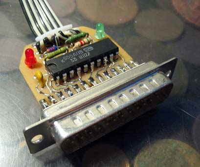
In general, there is a great number of programmers, differing in complexity of assembly, speed of firmware and reliable operation. The simplest of these is the variant, commonly called the “Five Wires”. But its reliability leaves much to be desired, since it will be easier to kill the LPT port =) More and more reliable is the STK200 programmer, which contains a buffer chip and ensures normal operation with the port.
')
But because of the presence of a chip, it becomes much more difficult to manufacture for a beginner (that is, for me).
How to deal with it?
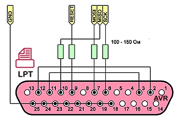
To protect against short circuits, we add 150 Ohm resistors, for compatibility with the STK200 (this will allow working with most firmware programs), connect pins 2 from 12 and 3 from 11 to LPT. As you can see, the circuit was not complicated at all and at the same time additional protection appeared.
Getting started!
On a male-style LPT connector (you can take it from an ancient cable to the printer) you need to connect legs from 18 to 25 — these are ground outlets. To protect against static between the ground and the body of the LPT connector, you can additionally solder a resistor of 1 KΩ.
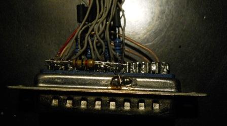
Then you need to connect output 3 to output 11 and output 2 to output 12 (hallmark STK200)
Resistors with nominal values from 100 to 150 Ohms are soldered to legs of 6, 7, 9, 10. These will be our 4 signal outputs.
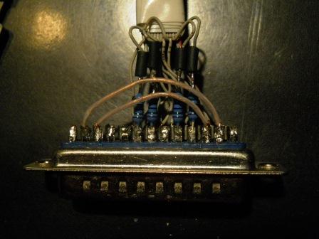
The loop can be taken from IDE, the length is better to choose without fanaticism, 20-30 centimeters should be enough =) The shorter, the more reliable the programmer will be in the end. It is good practice to alternate each signal wire with the ground (as was done, for example, in the same IDE cable) to protect against possible interference.
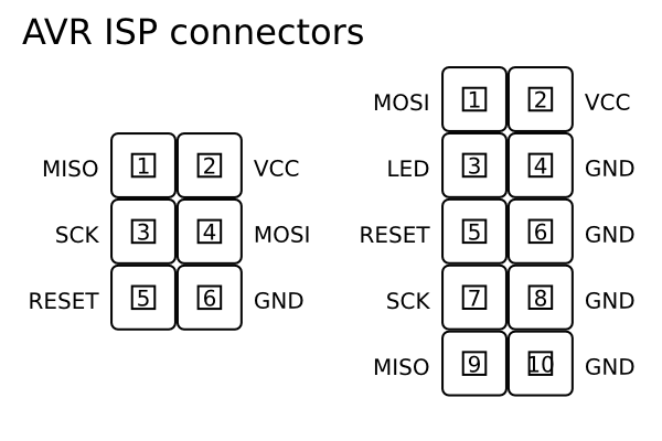
In-circuit programming connectors ...
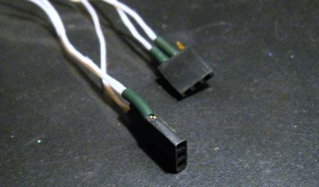
Here you can let fantasies go wild =) You can split a group of 2 × 3 from an IDE loop, you can use the BLS connectors of the “mother” type (they connect the front panel of the case to the motherboard). I cut two strips of 3 pins from a 40-pin ruler. It turned out not worse =)
After spikes of all this stuff, we close the LPT connector and admire the creation of our hands.

In general, there is a great number of programmers, differing in complexity of assembly, speed of firmware and reliable operation. The simplest of these is the variant, commonly called the “Five Wires”. But its reliability leaves much to be desired, since it will be easier to kill the LPT port =) More and more reliable is the STK200 programmer, which contains a buffer chip and ensures normal operation with the port.
')
But because of the presence of a chip, it becomes much more difficult to manufacture for a beginner (that is, for me).
How to deal with it?
To protect against short circuits, we add 150 Ohm resistors, for compatibility with the STK200 (this will allow working with most firmware programs), connect pins 2 from 12 and 3 from 11 to LPT. As you can see, the circuit was not complicated at all and at the same time additional protection appeared.
Getting started!
On a male-style LPT connector (you can take it from an ancient cable to the printer) you need to connect legs from 18 to 25 — these are ground outlets. To protect against static between the ground and the body of the LPT connector, you can additionally solder a resistor of 1 KΩ.
Then you need to connect output 3 to output 11 and output 2 to output 12 (hallmark STK200)
Resistors with nominal values from 100 to 150 Ohms are soldered to legs of 6, 7, 9, 10. These will be our 4 signal outputs.
The loop can be taken from IDE, the length is better to choose without fanaticism, 20-30 centimeters should be enough =) The shorter, the more reliable the programmer will be in the end. It is good practice to alternate each signal wire with the ground (as was done, for example, in the same IDE cable) to protect against possible interference.
In-circuit programming connectors ...
Here you can let fantasies go wild =) You can split a group of 2 × 3 from an IDE loop, you can use the BLS connectors of the “mother” type (they connect the front panel of the case to the motherboard). I cut two strips of 3 pins from a 40-pin ruler. It turned out not worse =)
After spikes of all this stuff, we close the LPT connector and admire the creation of our hands.
Source: https://habr.com/ru/post/137740/
All Articles