Satellite speedometer on STM32F1 and FreeRTOS
 The article focuses on the self-made speedometer, which receives information about the current speed of the car, its coordinates and time from GPS satellites. The article also, I hope, will help by taking the first steps in mastering 32-bit microcontrollers with the Cortex M core and wants to master one of the real-time operating systems (RTOS) for use in their own work.
Hardware implementation
He sat for himself, wrote in assembler under the 16th and 18th pic'ki, but did not know grief. But it's time to move on, explore the 32-bit microcontrollers. The choice fell on STM32 (namely - with the ARM Cortex M3 core) as the most promising - the volume of articles on them is growing exponentially in runet, microcontrollers are very attractive in price with a large amount of functional possibilities, they have great promise. With the growth of the project, you can transfer the work to much more productive versions of this kernel - from Cortex M to Cortex A. In addition, Apple uses iPad in its iPhones, the same core - ARM Cortex. Only more powerful, "A."
As a debugging board, on which he implemented a satellite speedometer, he took one of the HY Redbull clones on ebee for ~ $ 70:

')
Board, besides exploring the microcontroller STM32F103VCT6 (72MHz, 512KB FLASH, 64kb SRAM, 3ATSP, 2TSAP, DMA, FSMC, 5xUSART, 2xI2C, 3xSPI, CAN, USB 2.0 FS, etc.) and its built-in peripherals, allows you to master the basic prevalence outer periphery - MP3 / WMA decoder VS1003, Ethernet controller ENC28J60, LCD screen 3.2 ”with touchscreen (controller SSD1289), SD cards (under the card connector), USB, CAN, RS232 / 485, controller CH376 (implements the interface USB-Host / SD <-> UART / SPI / 8bit parallel for connecting to a sd card and a USB flash drive).
You can upload firmware in the STM32 through the UART, i.e. in fact, a programmer as such is not required. But it is much more convenient to use debugging tools for which the JTAG port on the board is intended. You can spend another 20-50 dollars on a JTAG debugger, but it is much more expedient to take a native ST debug board with a built-in debugger of Discovery series. It costs from $ 10 (and while this is really all, the basis of what is necessary for the development of STM32). As a debugger for JTAG, I took the STM32F4-Discovery debugger for myself (generally speaking, I got it for free as a seminar visitor, and it costs about 600 rubles):
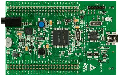
- designed for debugging ARM Cortex M4 (STM32F407), onboard built-in debugger (jumpers can be switched from debugging stm32f407 to debugging an external SWD card, which I used by connecting my firebull board to a JTAG connector via SWD). This microcontroller can already work at a frequency of 168 MHz (although the gem of revision “A” was caught, damp, in this revision the performance drop is due to the memory accelerator). Flash 1MB, 128KB RAM. From the built-in peripherals, USB device / host / OTG, 10/100 Ethernet, camera interface (up to 1Mpix can be connected), hardware CRC counting, DSP-processor deserve attention. From the external periphery, there is a MEMS accelerometer LIS302DL, a digital MEMS microphone MP45DT02, an ADC with I2S interface CS43L22. Many examples go to the board, among which I especially liked the voice recorder that works with a connected USB flash drive (a demonstration of the usb otg, mems microphone, audio i2s dac).
In terms of the choice of GPS-receiver was unoriginal. Took a very common EB-500. In order not to suffer when unpacking the board, I immediately took the EB-500 EVB Kit with an active antenna in the kit:
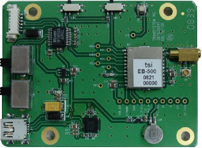
The receiver itself outputs data through the UART. But thanks to the UART-USB converter based on the CP2102, you can connect the board immediately via USB. Included is the EB View software, which demonstrates the capabilities of the chip. You can see the output of NMEA data, specify the list of fields that the chip needs to output, the frequency of their output, try out AGPS, and much more. It is possible through the Serial Port Monitor to see the dialogue of the EB View communication with the eb-500, and implement the appropriate setting of the eb-500 at the start of your device. Well, or study the datasheet) Also on the board is already present 3 volt battery for storing the almanac, when the device is turned off. For the subsequent quick start.
I also bought several loops for switching these boards - www.dealextreme.com/p/30cm-breadboard-wires-for-electronic-diy-40-cable-pack-80207#open%20full%20view - I recommend, the thing is extremely useful and convenient .
Software implementation
I chose Keil for myself. Convenient, widespread, equipped with an abundance of examples ... In a word - “mine”. :) I used the GLCD library attached to the Firebull board.
 I chose FreeRTOS as a real-time operating system (RTOS) - there is a sea of literature on it, it is actively developing, and due to these and other factors, uC / OS, scmOS, etc. turn out to be the preferred option. Plus supports both preemptive and corporate, and combined modes of operation. And to me, as a beginner, this is a plus. :) If you are not familiar with RTOS at all, but you want to get acquainted with the example of working with FreeRTOS and start using in your projects, then there is a very good article that helped me: microsin.net/programming/ARM/freertos-part1.html - all that need to start, it is described. Then it remains to download the FreeRTOS distribution, take from there a ready-made example for your microcontroller, modify it, and enjoy its work. Everything turns out to be not so difficult in practice, as it seems at first glance. :)
Now let's consider the source code of the satellite speedometer, which receives data from the EB-500 GPS receiver and outputs it to a 3.2 ”LCD screen:
int main(void)
{
prvSetupHardware();
vSemaphoreCreateBinary( xBinarySemaphore );
if (xBinarySemaphore != NULL){
xTaskCreate( vLEDTask, ( signed char * ) NULL , LED_TASK_STACK_SIZE , NULL , LED_TASK_PRIORITY , NULL );
xTaskCreate( vGPSTask, ( signed char * ) NULL , GPS_TASK_STACK_SIZE,NULL , GPS_TASK_PRIORITY , NULL );
//
vTaskStartScheduler();
}
return 0;
}
- create a semaphore (more about it - below). Run 3 tasks with different priorities. We will have vLEDTask () with the lowest priority - to blink the LED (“I'm alive, not stuck!”) and display the current system time on the screen.
vGPSTask () is a higher priority, after launch it is banal ... it falls asleep, waiting for the semaphore to be received.
prvSetupHardware () does the following:
static void prvSetupHardware( void ){
SysTick_CLKSourceConfig( SysTick_CLKSource_HCLK );// HCLK
NVIC_Configuration();//
GPIO_Configuration();// /,
USART2_9600(); //UART2 GPS EB-500, 9600/
RTC_Init();//
LCD_Initializtion();//
LCD_Clear(Blue);// -
}
First, we set the HCLK to clock the kernel, configure the NVIC interrupt controller (we need to enable an interrupt when receiving data on USART2), GPIO, USART2 pins (to which a GPS receiver is connected) to 9600 baud, 1 stop bit, no parity, 8 bits, and The last line - RTC_Init () - turn on the integrated RTC peripherals - to display the current time and date. And if you also stick a battery on the board, then there will be a real opportunity not to lose time when the power is turned off. :)
Interrupt handlers are specified in the stm32f10x_it.c file under the name in which they are indicated in the assembler startup _ *. S - file. I needed only one handler - interrupts for receiving bytes from USART2 from a gps receiver:
void USART2_IRQHandler(void)
{
static portBASE_TYPE xHigherPriorityTaskWoken;
if (USART_GetITStatus(USART2, USART_IT_RXNE) != RESET){// –
IrqBuf[IrqBuf_idx++]=USART_ReceiveData(USART2);// EB-500
if (IrqBuf_idx==BUFSIZE){//
IrqBuf_idx=0;
}
else if (IrqBuf[IrqBuf_idx-1]==0x0A){//
IrqBuf[IrqBuf_idx]=0x00;
IrqBuf_idx=0;
xHigherPriorityTaskWoken = pdFALSE;
xSemaphoreGiveFromISR( xBinarySemaphore, &xHigherPriorityTaskWoken );
}
USART_ClearITPendingBit(USART2, USART_IT_RXNE);//
}
}
- In the interrupt handler, we perform a check at the end of the line. If you find the newline character 0x0A, then you can parse the string with NMEA data from the EB-500. Directly in the interrupt handler, it is ideologically incorrect to carry out all processing, and sometimes it is simply dangerous — you may not have time before the next interruption occurs. The processing was delivered to a separate task with the highest priority - vGPSTask (), but the task is “asleep”, waiting for the semaphore to be received. And xSemaphoreGiveFromISR () in the interrupt handler is responsible for its output. We set the semaphore, reset the interrupt flag, and exit the handler - immediately control is passed to vGPSTask (), even if another task was being processed before the interrupt occurred, since this one gets the right to execute thanks to getting the semaphore.
The processing of NMEA data begins, namely, we are interested in the following lines from the EB-500:
$GPRMC,161229.487,A,3723.2475,N,12158.3416,W,0.13,309.62,120598,,*10
$GPVTG,309.62,T,,M,0.13,N,0.2,K*6E
$GPGGA,161229.487,3723.2475,N,12158.3416,W,1,07,1.0,9.0,M,,,,0000*18
- each such parcel ends with a checksum (* 10, * 6E, * 18) and line feeds (0x0D, 0x0A). All data is considered relevant only when there is an “A” in $ GPRMC (as in the example above). Otherwise, we get "V". With “V” in our example, “no signal” is displayed on the screen. Next, parse and display the data:
* we pull out the current time from the $ GPRMC package in the hhmmss.sss format (in the example above, this is 161229.487)
* from the $ GPVTG package we get the current speed in kilometers per hour (0.2, K - 0.2 kilometers per hour)
* from the $ GPGGA package we get the geographical longitude and width in the format ddmm.mmmm / dddmm.mmmm (in the example, the latitude is 3723.2475, the longitude is 12158.3416)
The full source code of the project is in the archive at the end of the article. I note that the example is not without flaws, the main one being that both tasks address the same hardware resource. You can solve it through mutexes or by writing a gatekeeper. I leave the decision interested in the quality of homework. But you can use an example without it - everything will work ...
Operating the system in my car gave positive results. Even if I start the car on a cold one, there are no problems with powering the board (hello to a down-converter dc-dc converter based on MC34063). The eb-500 cold start was 20 and 0.5 minutes hot. As expected, when stationary, there is a drift of coordinates - and accordingly speeds of up to 0.5, and sometimes up to 7 km / h. For mobile devices, this can be neglected, but for a homemade satellite alarm system based on the sim900 gsm-module, on which I work, this is a tangible problem. A positive moment - only thanks to this speedometer, I learned that the regular speedometer of my car is in a hurry at 5km / h.
Now it’s time for a photo shoot of a homemade satellite speedometer:


- 16:45:03 on the screen is UTC time. To transfer to Moscow, you need to add 4 hours (because we have canceled the transition to winter time). Those. I actually took this picture yesterday at 19:45. Geographical coordinates - in hour coordinates (hh.mm.ss.ms). that is, in the first row of coordinates, these are 55 hours, 48 minutes, 22 seconds and 830 milliseconds. To find this place, for example, via Yandex maps, we translate the coordinates into the required format: 55.48.22.830 = 55 + 48/60 + 22/3600 + 830/3600000 = ~ 55.806342 (rounded to the sixth decimal place). For the geographical width is the same: 37.24.22.51 = 37 + 24/60 + 22/3600 + 510/3600000 = ~ 37.406253. We hammer in the resulting value - 37.406253,55.806342 - into the Yandex.Map search string and get the result: maps.yandex.ru/?text=37.406253%2C55.806342&sll=&sspn=&z=&source=form
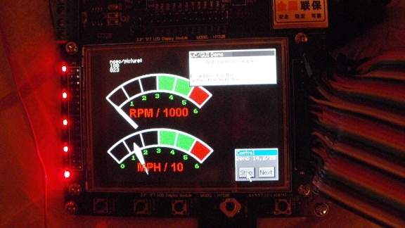
Using the graphical library uC / GUI, you can further develop this example. Display a graphic speedometer (and at the same time, by connecting to the ignition coil through a resistive divider to the stm32 ADC, and tachometer, you’ll have some kind of digital car dashboard):
And you can make your own navigator (yes, not easy, but nothing is impossible):

In the GLCD library, the archive already has a USER / GLCD / GLCD_UCGUI.c file, which is an interface for connecting uC / GUI to this and some other graphical screens. Download in the internet itself uC / GUI think is not difficult. So before you all the necessary tools to develop this example into something much more useful.
In the next article we will discuss the further development of this work, for the automation of cars and homes - a system that combines the concepts of "Smart Home", "Smart Car", and including the eCall / ERA-Glonass rescue system.
The project in Keil given in the article can be downloaded here .
Source: https://habr.com/ru/post/137673/
All Articles