Mechanical display on the Arduino - work on the bugs
The mechanical display of Lego and Arduino , about which I wrote in early January, turned out to be, in my opinion, quite good for the construction assembled in the evening. However, in the comments rightly pointed out the possibility of improving it. At the same time, reading the reviews, I learned what “POV” is, thanks to everyone who responded!
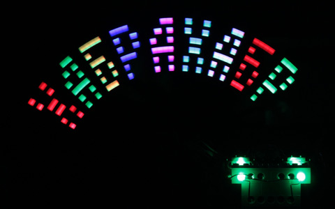
Over the past four weeks, the design was able to be finalized, and this is what happened as a result:
')
It turned out to be the easiest to improve mechanical stability - the child borrowed Duplo cubes (double-sized lego compatible with the standard one), and a solid and heavy platform was assembled from them. After that, he extended the crank and raised the swing bar with LEDs, thereby increasing the horizontal resolution. At first I thought of putting a more powerful motor, but it was enough to replace the batteries with a stabilized power supply and a slight increase in voltage. At 10.3 volts, my design makes exactly 6 full vibrations per second.

In the foreground, you can see two optical pairs - now you can catch the beginning of the reverse stroke.
Making the color display seemed like an easy task - just replacing the single color LEDs with RGB. No sooner said than done. Common anodes were connected to the data bus through limiting resistors, and the cathodes were soldered together in color and connected to the outputs of the Arduino responsible for color selection. When all eight LEDs are lit, up to 39 milliamps flow through each color picker wire, while the Arduino can have a maximum of 40. For guarantee, I added three MOSFET IRF 540 transistors - one for each color. It turned out about this scheme (only three RGB LEDs are shown):

Swinging strap connected to the controller 8 + 3 thin wires. Quite a lot, but if they are carefully laid, they do not interfere with the movement.
We supply a logical unit to the desired anode (D6-D13), with the same unit we open the color transistor (D0-D2) and the LED lights up. If 001 is applied to the color control outputs, red lights up, 010 - green, 011 ... again red, although yellow was expected.
Reading the datasheet showed that the red LED lights up at a voltage of 2.0 volts, while green and blue need 3.2. As a result, after the red diode is opened, the voltage practically does not increase, only the current increases, and the green and blue do not open. I could not find a solution to the problem for the given connection circuit with current-limiting resistors in the anode circuit. If you connect the resistors to the cathodes, then each diode will drop its own required voltage, but the resistors will need 24 pieces, which is too heavy for my mobile design. Google found several LED driver IC chips, but I didn’t have them on the farm. As a result, bypassed the problem programmatically, quickly turning on the colors in turn. With a delay of 50 microseconds per color, during the display of one pixel, elementary colors have time to change many times and merge into one.
In a stationary position, the device now shows the expected colors, it's time to test it in motion. I start the engine, and discover the following problem:

In the RGB LED, the red and blue elements are on opposite sides of the case, and as a result, instead of the lilac color, we get two clearly distinguishable individual stripes — red and blue. At the junction of the red and green areas, the difference in the location of the light-emitting points is also clearly visible. This problem was completely solved by replacing transparent LEDs with matte ones.

The elongation of the plank and the increase in its scope increased the theoretical number of pixels, but did not at all solve the problem of uneven movement. In the extreme right position for about two tens of milliseconds, the LEDs are almost immobile, while on the left they instantly change the direction of motion to the opposite. The motor is not ideal and the rotational speed depends on the load. Flexible plastic and backlash in connections finally confuse the picture. I last opened the textbook on theoretical mechanics fifteen years ago, so I did not even try to calculate the dynamics of the movement of my display, and immediately decided to measure how it behaves in reality. It turned out to be not so difficult: I put a mask in front with evenly spaced holes, sent a bright lamp to it, and fixed a photoresistor at the end of the bar.

It remains to write a simple program that first makes several idle cycles and averages their period for accuracy, and then collects data on the illumination of the photodiode through the ADC. Each measurement is accompanied by a call to the micros function, which gives the number of microseconds that have passed. The array of data on the serial port pumped into the computer and analyzed in Excel.
Here is what the voltage on the photoresistor looks like - it is perfectly visible when light strikes it through the holes in the mask:

But the nonlinearity in all its glory, it is good that he did not try to simulate it and calculate:

Excel is able to approximate arbitrary data sets with polynomials up to the fifth order, so after a few minutes in my hands was the cherished formula describing motion:

Here y is the delay in microseconds from the beginning of the cycle, x is the number of the virtual pixel varying from 1 to 20 (I had 20 holes in the calibration mask). By giving x fractional values, you can calculate delays for arbitrary resolution. I stopped at 54 pixels.
To test the formula, I wrote a simple little program that outputs 0x55 and 0xAA alternately to highlight pixels in a checkerboard pattern.

Ekselevskaya mathematics did not fail, and there are no complaints about the uniformity of the step of the raster, but the pixels themselves turned out instead of rectangular oval. Not surprising, because the formula calculates the delays for the center of the ideal pixel, and the real LED has 5 mm in diameter, and illuminates the surrounding areas. Rectangular pixels are easier to paint with rectangular LEDs, which I achieved by sticking an opaque adhesive tape on the sides:

The control "chessboard" confirmed that it is so much better indeed:

The algorithm is simple and no difficulties were foreseen, however, at a certain moment of writing the code, the program began to give strange, unpredictable results. It turned out that the RAM was running out, which in Arduino UNO is only two kilobytes. The microcontroller does not follow the memory allocation of the operating system, so it does not notice any errors and does not signal an overflow. I assumed that the arrays declared as const are stored in Flash memory, but it turned out that this is not the case. More precisely, they first really lie in permanent memory, but they are copied into RAM at startup, although they cannot be changed. To avoid this, variables need to be declared via PROGMEM, an article on the Arduino website was found about it. In general, "read mana, they rulez."
It is inconvenient to draw letters in points, so I put the character generator table in the same PROGMEM and wrote the function of drawing letters. There are no problems with English characters, but instead of the Russians, rubbish was displayed. VisualStudio 2010 with the Visaul Micro Arduino plug-in was used as the development environment. Despite the fact that the source files were saved in Win1251 (one byte per character), the string
Announced an array of 27 + 1 bytes in length, in which each triple had the same content, has nothing to do with the source text. The same code from under the Arduino UNO environment writes two bytes per Russian character, most likely in UTF8. We managed to get around the problem by encoding the string character-by-character:
Now, as expected, we get 9 bytes of text plus one more for the final zero. Run the program and see ... very different characters. The study showed that the large Russian letter “A” is compiled into code 144, which does not correspond to the code 192 expected for Win1251. It was not lazy and
read on the Internet about possible encodings of Russian letters , including very exotic ones. None of them has A broadcast to 144. The only explanation that comes to mind is the representation of Russian letters in Unicode, after which the low byte is cut from the letter A (U + 0410), to which for some reason 128 are added. Why is it so? , but after adding the necessary constant to the code of the letters, they fell into place.
Here's what happened in the end:


And what about without him?
With a cycle duration of 170 milliseconds, almost six frames per second are obtained. At the same camera - 30 frames per second, and because of the frequency multiplicity on the video, there is a noticeable strong flicker. If you look with your eyes, the picture looks much more stable.
Image output during the reverse course of the scan has not yet been programmed. This would double the frame rate, but would complicate the programming of animation and text scrolling. When drawing only during a forward stroke, the microcontroller has as much as 80 milliseconds to slowly calculate the next frame.
Identified deficiencies
- The small size of the "screen" is insufficient for writing the word "Habrahabr"
- Monochrome
- Pixel pitch irregularity calculated by simply dividing the cycle time by resolution
- Disappointment with habouriers who were waiting to see the video
- The need to manually bitwise encode the image of each letter
- General instability of the design - “display” at work swings heavily
- Idle reverse strips with LEDs. They are highlighted only when driving from right to left.
Over the past four weeks, the design was able to be finalized, and this is what happened as a result:
')
Bug work
Stability and size
It turned out to be the easiest to improve mechanical stability - the child borrowed Duplo cubes (double-sized lego compatible with the standard one), and a solid and heavy platform was assembled from them. After that, he extended the crank and raised the swing bar with LEDs, thereby increasing the horizontal resolution. At first I thought of putting a more powerful motor, but it was enough to replace the batteries with a stabilized power supply and a slight increase in voltage. At 10.3 volts, my design makes exactly 6 full vibrations per second.
In the foreground, you can see two optical pairs - now you can catch the beginning of the reverse stroke.
Colour
Making the color display seemed like an easy task - just replacing the single color LEDs with RGB. No sooner said than done. Common anodes were connected to the data bus through limiting resistors, and the cathodes were soldered together in color and connected to the outputs of the Arduino responsible for color selection. When all eight LEDs are lit, up to 39 milliamps flow through each color picker wire, while the Arduino can have a maximum of 40. For guarantee, I added three MOSFET IRF 540 transistors - one for each color. It turned out about this scheme (only three RGB LEDs are shown):
Swinging strap connected to the controller 8 + 3 thin wires. Quite a lot, but if they are carefully laid, they do not interfere with the movement.
Rake number one
We supply a logical unit to the desired anode (D6-D13), with the same unit we open the color transistor (D0-D2) and the LED lights up. If 001 is applied to the color control outputs, red lights up, 010 - green, 011 ... again red, although yellow was expected.
Reading the datasheet showed that the red LED lights up at a voltage of 2.0 volts, while green and blue need 3.2. As a result, after the red diode is opened, the voltage practically does not increase, only the current increases, and the green and blue do not open. I could not find a solution to the problem for the given connection circuit with current-limiting resistors in the anode circuit. If you connect the resistors to the cathodes, then each diode will drop its own required voltage, but the resistors will need 24 pieces, which is too heavy for my mobile design. Google found several LED driver IC chips, but I didn’t have them on the farm. As a result, bypassed the problem programmatically, quickly turning on the colors in turn. With a delay of 50 microseconds per color, during the display of one pixel, elementary colors have time to change many times and merge into one.
Rake number two
In a stationary position, the device now shows the expected colors, it's time to test it in motion. I start the engine, and discover the following problem:
In the RGB LED, the red and blue elements are on opposite sides of the case, and as a result, instead of the lilac color, we get two clearly distinguishable individual stripes — red and blue. At the junction of the red and green areas, the difference in the location of the light-emitting points is also clearly visible. This problem was completely solved by replacing transparent LEDs with matte ones.
Mechanical scan
The elongation of the plank and the increase in its scope increased the theoretical number of pixels, but did not at all solve the problem of uneven movement. In the extreme right position for about two tens of milliseconds, the LEDs are almost immobile, while on the left they instantly change the direction of motion to the opposite. The motor is not ideal and the rotational speed depends on the load. Flexible plastic and backlash in connections finally confuse the picture. I last opened the textbook on theoretical mechanics fifteen years ago, so I did not even try to calculate the dynamics of the movement of my display, and immediately decided to measure how it behaves in reality. It turned out to be not so difficult: I put a mask in front with evenly spaced holes, sent a bright lamp to it, and fixed a photoresistor at the end of the bar.
It remains to write a simple program that first makes several idle cycles and averages their period for accuracy, and then collects data on the illumination of the photodiode through the ADC. Each measurement is accompanied by a call to the micros function, which gives the number of microseconds that have passed. The array of data on the serial port pumped into the computer and analyzed in Excel.
Here is what the voltage on the photoresistor looks like - it is perfectly visible when light strikes it through the holes in the mask:
But the nonlinearity in all its glory, it is good that he did not try to simulate it and calculate:
Excel is able to approximate arbitrary data sets with polynomials up to the fifth order, so after a few minutes in my hands was the cherished formula describing motion:
Here y is the delay in microseconds from the beginning of the cycle, x is the number of the virtual pixel varying from 1 to 20 (I had 20 holes in the calibration mask). By giving x fractional values, you can calculate delays for arbitrary resolution. I stopped at 54 pixels.
Pixels
To test the formula, I wrote a simple little program that outputs 0x55 and 0xAA alternately to highlight pixels in a checkerboard pattern.
Ekselevskaya mathematics did not fail, and there are no complaints about the uniformity of the step of the raster, but the pixels themselves turned out instead of rectangular oval. Not surprising, because the formula calculates the delays for the center of the ideal pixel, and the real LED has 5 mm in diameter, and illuminates the surrounding areas. Rectangular pixels are easier to paint with rectangular LEDs, which I achieved by sticking an opaque adhesive tape on the sides:
The control "chessboard" confirmed that it is so much better indeed:
Programming
The algorithm is simple and no difficulties were foreseen, however, at a certain moment of writing the code, the program began to give strange, unpredictable results. It turned out that the RAM was running out, which in Arduino UNO is only two kilobytes. The microcontroller does not follow the memory allocation of the operating system, so it does not notice any errors and does not signal an overflow. I assumed that the arrays declared as const are stored in Flash memory, but it turned out that this is not the case. More precisely, they first really lie in permanent memory, but they are copied into RAM at startup, although they cannot be changed. To avoid this, variables need to be declared via PROGMEM, an article on the Arduino website was found about it. In general, "read mana, they rulez."
Russification
It is inconvenient to draw letters in points, so I put the character generator table in the same PROGMEM and wrote the function of drawing letters. There are no problems with English characters, but instead of the Russians, rubbish was displayed. VisualStudio 2010 with the Visaul Micro Arduino plug-in was used as the development environment. Despite the fact that the source files were saved in Win1251 (one byte per character), the string
char* text = "";
Announced an array of 27 + 1 bytes in length, in which each triple had the same content, has nothing to do with the source text. The same code from under the Arduino UNO environment writes two bytes per Russian character, most likely in UTF8. We managed to get around the problem by encoding the string character-by-character:
char russianText[] = {'', '', '', '', '', '', '', '', '', '\0'};
Now, as expected, we get 9 bytes of text plus one more for the final zero. Run the program and see ... very different characters. The study showed that the large Russian letter “A” is compiled into code 144, which does not correspond to the code 192 expected for Win1251. It was not lazy and
read on the Internet about possible encodings of Russian letters , including very exotic ones. None of them has A broadcast to 144. The only explanation that comes to mind is the representation of Russian letters in Unicode, after which the low byte is cut from the letter A (U + 0410), to which for some reason 128 are added. Why is it so? , but after adding the necessary constant to the code of the letters, they fell into place.
Here's what happened in the end:
Video
And what about without him?
With a cycle duration of 170 milliseconds, almost six frames per second are obtained. At the same camera - 30 frames per second, and because of the frequency multiplicity on the video, there is a noticeable strong flicker. If you look with your eyes, the picture looks much more stable.
What's next?
Image output during the reverse course of the scan has not yet been programmed. This would double the frame rate, but would complicate the programming of animation and text scrolling. When drawing only during a forward stroke, the microcontroller has as much as 80 milliseconds to slowly calculate the next frame.
Source: https://habr.com/ru/post/137444/
All Articles