Linux head-end computer - collect it yourself!
This article focuses on the self-made head-on computer with the hard-to-name WXHMD, created by a Parisian craftsman named Pascal. This is a Gumstix Overo Fire computer-on-module computer mounted on the Vuzix VR920 head-mounted display. The result was a 640x480 stereoscopic image device with audio input and audio output, 3D tilt sensors (3D tilt sensor), 3D magnetic compass, TI OMAP3530 @ 600 MHz processor, Linux OS, WiFi, Bluetooth. Power - 1 amp @ 3.7 volts. Weight - 180 grams.

')
To connect a single-board computer with a head-mounted display, it was necessary to design a small board with power connectors, USB and simple digital-to-analog converters (DACs) for analog video output. DACs are connected to the video output of the computer and create a 12-bit analog signal at the output (4 bits per color component each). Synchronization signals from the LCD-out are sent directly to the corresponding VGA-contacts (VR 920 could work with a signal of 1.8V, although nominally it should be 5V). Everything else is done by software on OMAP. Actually, OMAP cannot generate fully VGA-compatible synchronization signals (perhaps HSYNC pulses are insufficiently long), but the VR920 also works with such "wrong" signals.

Fig.1. Scheme: wxhmd.sch , wxhmd.sch.pdf
The double-sided printed circuit board was designed in gEDA gschem, diluted in gEDA PCB, and etched using Direct Inkjet Resist Printing technology (read more about it here ).
The pinout and footprint of Overo had to be converted to the format gEDA: OVERO.sym , OVERO.fp . These files are derived from specifications published by the Gumstix under the Creative Commons Attribution-ShareAlike2.5 license. Some of the work was done by hand, so it may contain errors.

Fig.2. Layout : wxhmd-2.pcb , wxhmd-2.pcb.pdf
Since the OTG USB port in Overo delivers only 100 mA, the head-mounted display is powered via VSYSTEM instead of USBOTG_VBUS.

Fig.3. Testing performance before embedding boards in the VR920
Starting work on the device, the author assumed that the 13-pin connector inside the VR920 would receive “raw” (USB) and USB VGA signals. But it turned out that the cable splitting into two tails (USB and VGA) contains a small board that processes VGA sync signals.
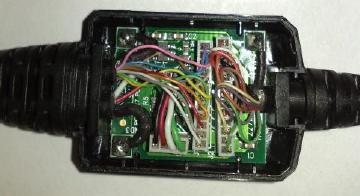
Fig.4. Board, "hidden" inside the cable
Pascal did not try to figure out whether OMAP could be forced to generate a suitable composite sync signal (apparently, it generates a nonstandard). The author just soldered this board to the computer board. In addition, the author could not find the connector corresponding to the head-mounted display connector (13 contacts with a step of 1 mm). The sacrificed cable solved both these problems.

Fig.5. Final preparations: video synchronization board soldered to computer board

Fig.6. Testing before final assembly
Usb The VR920 USB stack tells the host that it needs 500 mA, so Linux will immediately turn off the headrest. Usually this problem is solved by connecting an external powered USB hub. In our case, this is not the best solution, since the headguard is powered by VSYSTEM, we can make Linux ignore checking the power parameters of the USB device using usb_ignore_power.patch without any threat to the system’s performance.
Frame buffer In the u-boot environment, you need to set the Linux framebuffer resolution to be 640x480.
OMAP LCD configuration. These commands configure the OMAP LCD subsystem to generate VGA-like signals:
Hid The most correct way is to interact with the accelerometer (tilt sensors) of the headband via / dev / hidraw. This will require recompiling the Gumstix Linux kernel with CONFIG_HIDRAW = y. Sensor readings can be read in 17-byte chunks containing six 16-bit values (little-endian):

Fig.7. Colored rectangles (on the left - the original image, on the right - in the cap)
Smooth color transitions do not work, even when using resistors of the E12 series (with an accuracy of 10%). It may be worth using not 4, but 5 or more bits per color component.
Comment LJ user 0x8 :
“The article mentioned problems with DACs on resistors. For smoother transitions, more bits of the DAC are needed, not 4 bits per channel, but 6, say (this was the capacity of the first TFT monitors).
To resist less heat - to increase their resistance times 2 (but the display input should not consume a large current, otherwise you will have to fence the repeater on the transistor). And even in such circuits, resistors with a deviation of + -1%, rather than 10%, are strongly recommended. It is necessary for the linear transformation of the digital-analogue. The more discharges, the more critical the accuracy of resistance. In Soviet microcircuits, these resistors _after) the manufacture was cut on each chip with a laser to get into the nominal. "

Fig.8. Firefox on the head-mounted display (X11 launched remotely via WiFi)
Not the best quality of the above photos is explained not only by the use of the simplest DAC, but also by the fact that it is quite problematic to place the camera so that the image on the screen of the headgear is exactly in focus.
vroom920.c - a program that demonstrates a three-dimensional stereo image and work with tracking head position. It builds a wire image of a cylindrical room around the user.

Fig.9. vroom920 in the head-mounted display
Attention! This prototype may violate any technical standards and regulations regarding user safety and electromagnetic coupling.
DAC. It would be better to use quality DAC. Since this was the first “iron” project of the author, created using printed circuit boards using an inkjet printer, the author tried to avoid any complications by using the simplest DAC on resistors.
GPIO. The DAC on the resistors at the GPIO output, perhaps, slightly distorts the electrical parameters of OMAP, but the problem is not so much in this as in the fact that such DACs quickly heat up. If the resistors burn the same Overo, the author promises to write about it.
Battery life. The system consumes 1 amp - without optimizing energy consumption. This is quite acceptable, since there is hardly anyone willing to wear two working microwave transmitters on the head, a heavy lithium battery and glasses that block the view.
Improved design. The VR920 board has many tricky features that were not used in this project - support for various VGA modes and resolutions and even implements on-screen menus overlapping the image. Of course, you can remove all this and work directly with Kopin LCD modules. [VOGL2008] implemented this for a model with a resolution of 320x240, which has a slightly different analog RGB interface. The main difficulties here are working with 9-volt signals, the implementation of polarity inversion and the ZIF flex connector.
[PCBPRT] Experiments in inkjet PCB printing: http://www.pabr.org/pcbprt/pcbprt.en.html
[VOGL2008] Gumstix Video out board :: Kopin K230LV adapter: http://pervasive.researchstudio.at/portal/node/49
All rights to the structure described in this article and the photos included in the article belong to the author of the structure.
Translation of the article is made and posted with the consent of the author of the original article.
Original source: http://www.pabr.org/wxhmd/doc/wxhmd.en.html
1. Vuzix VR 920 is a high-quality head-on display priced at around 400 euros.
- two 640x480 Kopin display modules;
- analog video input DB15 VGA;
- powered by USB (nominally - 5 mA @ 5V, but it also works at reduced voltage, up to 3.7V);
- built-in stereo headphones and monaural microphone (USB audio profile);
- three-axis accelerometer and magnetometer (USB HID profile);
2. Single board computer Gumstix Overo Fire
- TI OMAP3530 processor, maximum 600 MHz, default 500 MHz
- 256 MB RAM, microSD flash card
- WiFi, Bluetooth
- USB OTG (maximum 100 mA)
- video output for LCD @ 1.8V
')
3. Connection board
To connect a single-board computer with a head-mounted display, it was necessary to design a small board with power connectors, USB and simple digital-to-analog converters (DACs) for analog video output. DACs are connected to the video output of the computer and create a 12-bit analog signal at the output (4 bits per color component each). Synchronization signals from the LCD-out are sent directly to the corresponding VGA-contacts (VR 920 could work with a signal of 1.8V, although nominally it should be 5V). Everything else is done by software on OMAP. Actually, OMAP cannot generate fully VGA-compatible synchronization signals (perhaps HSYNC pulses are insufficiently long), but the VR920 also works with such "wrong" signals.
Fig.1. Scheme: wxhmd.sch , wxhmd.sch.pdf
The double-sided printed circuit board was designed in gEDA gschem, diluted in gEDA PCB, and etched using Direct Inkjet Resist Printing technology (read more about it here ).
The pinout and footprint of Overo had to be converted to the format gEDA: OVERO.sym , OVERO.fp . These files are derived from specifications published by the Gumstix under the Creative Commons Attribution-ShareAlike2.5 license. Some of the work was done by hand, so it may contain errors.
Fig.2. Layout : wxhmd-2.pcb , wxhmd-2.pcb.pdf
4. Build
Since the OTG USB port in Overo delivers only 100 mA, the head-mounted display is powered via VSYSTEM instead of USBOTG_VBUS.
Fig.3. Testing performance before embedding boards in the VR920
Starting work on the device, the author assumed that the 13-pin connector inside the VR920 would receive “raw” (USB) and USB VGA signals. But it turned out that the cable splitting into two tails (USB and VGA) contains a small board that processes VGA sync signals.
Fig.4. Board, "hidden" inside the cable
Pascal did not try to figure out whether OMAP could be forced to generate a suitable composite sync signal (apparently, it generates a nonstandard). The author just soldered this board to the computer board. In addition, the author could not find the connector corresponding to the head-mounted display connector (13 contacts with a step of 1 mm). The sacrificed cable solved both these problems.
Fig.5. Final preparations: video synchronization board soldered to computer board
Fig.6. Testing before final assembly
5. Software
Usb The VR920 USB stack tells the host that it needs 500 mA, so Linux will immediately turn off the headrest. Usually this problem is solved by connecting an external powered USB hub. In our case, this is not the best solution, since the headguard is powered by VSYSTEM, we can make Linux ignore checking the power parameters of the USB device using usb_ignore_power.patch without any threat to the system’s performance.
Frame buffer In the u-boot environment, you need to set the Linux framebuffer resolution to be 640x480.
OMAP LCD configuration. These commands configure the OMAP LCD subsystem to generate VGA-like signals:
DISPLAY=:0.0 xset -dpms # LCD,
devmem2 0x480504fc w 0x00003000 # Polarities
devmem2 0x48050464 w 0x02f00f3f # HSYNC
devmem2 0x48050468 w 0x02000901 # VSYNC
devmem2 0x4805047c w 0x01df027f # Size
killall Xorg #
Hid The most correct way is to interact with the accelerometer (tilt sensors) of the headband via / dev / hidraw. This will require recompiling the Gumstix Linux kernel with CONFIG_HIDRAW = y. Sensor readings can be read in 17-byte chunks containing six 16-bit values (little-endian):
root@overo:~# hexdump -e '4/1 "%02x " 6/2 " %4d " 1/1 " %02x" "\n"' < /dev/hidraw0
00 02 02 00 -1 403 -60 82 421 189 ab
00 02 02 00 -9 374 -68 65 400 175 ab
00 02 02 00 -8 394 -65 62 396 174 ab
00 02 02 00 -19 378 -78 35 364 158 ab
6. Results
Fig.7. Colored rectangles (on the left - the original image, on the right - in the cap)
Smooth color transitions do not work, even when using resistors of the E12 series (with an accuracy of 10%). It may be worth using not 4, but 5 or more bits per color component.
Comment LJ user 0x8 :
“The article mentioned problems with DACs on resistors. For smoother transitions, more bits of the DAC are needed, not 4 bits per channel, but 6, say (this was the capacity of the first TFT monitors).
To resist less heat - to increase their resistance times 2 (but the display input should not consume a large current, otherwise you will have to fence the repeater on the transistor). And even in such circuits, resistors with a deviation of + -1%, rather than 10%, are strongly recommended. It is necessary for the linear transformation of the digital-analogue. The more discharges, the more critical the accuracy of resistance. In Soviet microcircuits, these resistors _after) the manufacture was cut on each chip with a laser to get into the nominal. "
Fig.8. Firefox on the head-mounted display (X11 launched remotely via WiFi)
Not the best quality of the above photos is explained not only by the use of the simplest DAC, but also by the fact that it is quite problematic to place the camera so that the image on the screen of the headgear is exactly in focus.
vroom920.c - a program that demonstrates a three-dimensional stereo image and work with tracking head position. It builds a wire image of a cylindrical room around the user.
Fig.9. vroom920 in the head-mounted display
7. In conclusion
Attention! This prototype may violate any technical standards and regulations regarding user safety and electromagnetic coupling.
DAC. It would be better to use quality DAC. Since this was the first “iron” project of the author, created using printed circuit boards using an inkjet printer, the author tried to avoid any complications by using the simplest DAC on resistors.
GPIO. The DAC on the resistors at the GPIO output, perhaps, slightly distorts the electrical parameters of OMAP, but the problem is not so much in this as in the fact that such DACs quickly heat up. If the resistors burn the same Overo, the author promises to write about it.
Battery life. The system consumes 1 amp - without optimizing energy consumption. This is quite acceptable, since there is hardly anyone willing to wear two working microwave transmitters on the head, a heavy lithium battery and glasses that block the view.
Improved design. The VR920 board has many tricky features that were not used in this project - support for various VGA modes and resolutions and even implements on-screen menus overlapping the image. Of course, you can remove all this and work directly with Kopin LCD modules. [VOGL2008] implemented this for a model with a resolution of 320x240, which has a slightly different analog RGB interface. The main difficulties here are working with 9-volt signals, the implementation of polarity inversion and the ZIF flex connector.
Bibliography
[PCBPRT] Experiments in inkjet PCB printing: http://www.pabr.org/pcbprt/pcbprt.en.html
[VOGL2008] Gumstix Video out board :: Kopin K230LV adapter: http://pervasive.researchstudio.at/portal/node/49
All rights to the structure described in this article and the photos included in the article belong to the author of the structure.
Translation of the article is made and posted with the consent of the author of the original article.
Original source: http://www.pabr.org/wxhmd/doc/wxhmd.en.html
Source: https://habr.com/ru/post/137420/
All Articles