MSP430, learn to program and debug hardware
Today, a respected user, I will try to fill in some space formed in MSP430 articles, namely, the basics and the approach to programming devices on this microcontroller.
This article is primarily aimed at newbies, as I will consider a number of fairly simple tasks, such as working with SPI, blinking a light bulb, and debugging in proteus.
Introduction
This article will discuss the device, which is based on the eZ430-RF2500 debug board. The board contains the MSP430F2274 microcontroller and the CC2500 wireless module, which, it should be noted, will not be discussed further.
My colleague, S. A. Sokolov, made a small add-in for this debug kit, it is attached to all the conclusions. On the superstructure is the accelerometer LIS331DLH, with which we will interact with SPI.

I should note that STMicroelectronics devices working on SPI are very similar and, accordingly, working with them will look about the same.
What we need
Development environment
First you need to download and install the development environment and compiler. To date, there are three options - Code Composer Studio , IAR Embedded Workbench for TI MSP430 and mspgcc .
I will use Workbench KickStart Edition. KickStart is free, it has a limit on the amount of code, but to study this is more than enough.
')
Debug Tool
If you do not have an oscilloscope or logic analyzer at hand, then there are often difficulties associated with misunderstanding what actually happens in your device. Understanding the reasons why the device refuses to work often helps Proteus.
It can find very many MSP430 microcontrollers. Unfortunately, there was no MSP430F2274 in Proteus, but there is an analogue - MSP430F2272, and we will use it.
Let's start writing code
Creating a project
At this stage, difficulties should arise. As a programming language, choose C ++.
- Replace the standard #include "io430.h" with #include "msp430f2274.h" (header file for our microcontroller);
- In the properties of the project on the Debugger tab, select Driver: FET Debugger;
- On the General Options tab in the Device window, select MSP430F2274;
- In order to make sure that everything is done correctly, press Ctrl + D (Download and Debug). As soon as the controller firmware is loaded, press F5 to execute it.
If you need to compile a file for Proteus, on the Debugger tab in the Driver window, select Simulator, and on the Linker Output tab in the Format window, select Other and Output format, select intel-standart, and in the Output file window, change the extension to hex.
Work with ports
The first thing to learn in a microcontroller is working with ports. Let's look at a small example.
#include "msp430f2274.h"
void main ( void )
{
WDTCTL = WDTPW + WDTHOLD ;
P1DIR & = ~ BIT2 ;
P1REN | = BIT2 ;
P1DIR | = BIT1 + BIT0 ;
while ( true )
{
if ( P1IN & BIT2 )
{
P1OUT | = BIT1 ;
P1OUT & = ~ BIT0 ;
}
else
{
P1OUT | = BIT0 ;
P1OUT & = ~ BIT1 ;
}
}
}
PxDIR is responsible for the direction of port 1. When a specific bit of this register is set to 0, the corresponding pin works as input. Conversely, if the corresponding bit is set to 1, then the pin works on the output. In the example, there are 3 pins: P1.2 - button, P1.0 - red LED, P1.1 - green LED.
PxREN includes an internal pull- up resistor. The button closes the pin to the ground, and, accordingly, puts it in the zero state. When the button is not pressed, the pin is not connected to anything and in order to provide a logical unit on it, it is required to connect it via a resistor to the power supply, which is what the P1REN register does.
PxIN and PxOUT contain the status of the port pins. By setting zero or one in the PxOUT register, we change the voltage on the microcontroller's foot, thereby turning the LED on and off. Reading a specific bit from the PxIN register, we get a logical signal, which is now fed to the pin.
PxSEL selects pin function. In the datasheet on the image of the microcontroller, functions are usually indicated by the sign “/”.
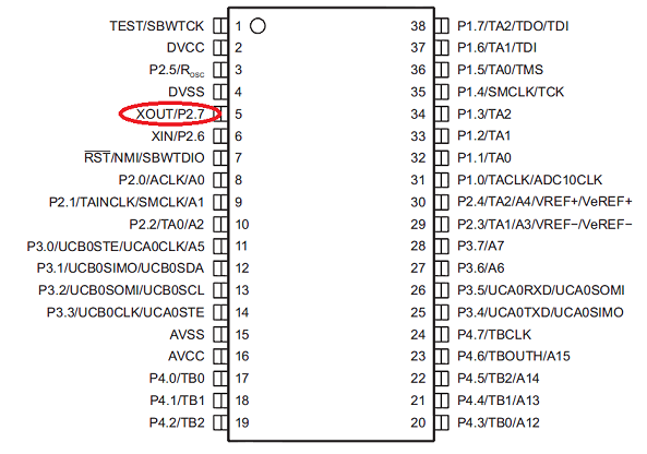
For example, in Figure P2.7 it works like a normal pin if P2SEL has 0 in the corresponding digit. By default, in this case, the unit is set there, which means that this foot is intended to connect an external watch crystal.
The constants BIT0..BITF are contained in the file msp430f2274.h and are 16-bit words in a given digit which contain 1, all other digits contain 0.
It should be noted that the msp430f2274.h file contains a lot of useful information. There are all the constants of the controller with comments in English.
In the example, bitwise C operations are used, “| =” will set the bit corresponding to the value on the right in the register to the left into one, and “& = ~” will set it to 0.
What happened:
Work with SPI
Immediately start with an example
#include "msp430f2274.h"
unsigned char spi ( unsigned char data, unsigned char dataEx = 0x00 ) ;
void main ( void )
{
WDTCTL = WDTPW + WDTHOLD ;
P1DIR | = BIT0 + BIT1 ;
P1OUT & = ~ BIT0 ;
P1OUT & = ~ BIT1 ;
P3SEL = BIT1 + BIT2 + BIT3 ;
P3DIR | = BIT0 ;
P3OUT | = BIT0 ; // Disable the CC2500 (set 1 to CS)
P2SEL & = ~ BIT6 ;
P2SEL & = ~ BIT7 ;
P2DIR | = BIT6 + BIT7 ;
P2OUT | = BIT6 ; // Turn off the temperature sensor (also connected to SPI)
P2OUT | = BIT7 ; // Disable Accelerometer
// Configure SPI
UCB0CTL0 | = UCMSB + UCMST + UCSYNC ;
UCB0CTL1 | = UCSSEL_2 ;
UCB0BR0 = 0x02 ;
UCB0BR1 = 0 ;
UCB0CTL1 & = ~ UCSWRST ;
if ( spi ( 0x8F ) == 0x32 )
{
P1OUT | = BIT1 ; // Red LED
}
P1OUT | = BIT0 ; // Green LED
}
unsigned char spi ( unsigned char data, unsigned char dataEx )
{
unsigned char RX ;
P2OUT & = ~ BIT7 ; // Turn On Accelerometer
while ( ! ( IFG2 & UCB0TXIFG ) ) ; // Waiting for send buffer
UCB0TXBUF = data ;
while ( ! ( IFG2 & UCB0RXIFG ) ) ; // Waiting for receive buffer
RX = UCB0RXBUF ;
while ( ! ( IFG2 & UCB0TXIFG ) ) ;
UCB0TXBUF = dataEx ;
while ( ! ( IFG2 & UCB0RXIFG ) ) ;
RX = UCB0RXBUF ;
P2OUT | = BIT7 ;
return RX ;
}
In the example, the register value is requested at the address 0x8F, it contains a code that identifies the device. This code is listed in the datasheet. This ensures that the data is exchanged. If successful, turn on the red LED.
Accordingly, all other devices connected to the SPI must be disconnected from the interface. For this, the CS on them is set to one.
Conclusion
Next time I will try to tell you more about working with LIS331DLH, get to interrupts, work with the USB-UART bridge built into the programmer and tell you a little about watchdog.
I hope this article has been helpful to you, reader.
Source: https://habr.com/ru/post/137205/
All Articles