In search of isophotes
I once needed the calculation of isophotes (lines of equal intensity on images), however, I did not find ready-made libraries, and I really didn’t want to dig into someone else’s code (for example, Octave or Iraf). As the simplest algorithm, I found the method of walking squares . However, this method greatly reduces the spatial resolution when calculating isophote nodes, so I decided to modify it a bit and make the squares overlap.
The first implementation (by the way, quite fast) was unsuccessful: I built a mask common to all levels, and for a particular level I recalculated separately, at the points through which several contour lines pass, we get gaps. Picking tricks on the code led to more and more interlocks and flags, so I decided to go to the detriment of performance and calculate the masks separately for each intensity level.
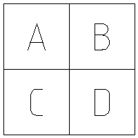
So, briefly, I will repeat what the “walking squares” method is. To construct isophotes of level I i , a special mask is first constructed: for each pixel of the image, the relative position of the “neighbors” is coded on the right, bottom and bottom right. You can encode it differently, I just presented the code as a 000abcd bit mask, where a, b, c and d are the relative intensities in the corresponding pixels (a is our current image pixel)
If the value in the pixel is greater than the level of the isoline, a unit is assigned to the corresponding bit, otherwise - zero. If w is the width of the image, and * in is a pointer to pixel a, then the mask value (* out) for this pixel is calculated as follows:
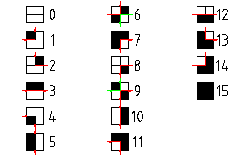
As a result, depending on the configuration of the pixels, we get one of 16 values:
The mask size is one less in both dimensions than the image size.
The next step is the sequential testing of all mask pixels for inequality of zero and 15. As soon as we find such a pixel, we begin to build an isoline from it. In order to build contour lines correctly, we need to memorize the direction from which we approached this pixel. In the figure above, the arrows indicate the possible paths of “derailment” from each pixel of the mask. If we do not take into account the forbidden direction (from which we came), we will either have to check the extra mask pixels, or else (in the case of special points 6 and 9, but about them a little later) we may in general incorrectly choose the position of the next isophotes.
As the mask pixels are viewed (from left to right and from top to bottom, if we consider the origin of the image in the upper left corner), until we find only empty cells, the “forbidden” direction is the “left” direction. As soon as we find a cell containing a section of the isoline, we, in accordance with a previously prepared array of "directions", choose the next direction, cutting off the "forbidden". If there are two such directions, we choose right or down (with priority on “right”) when moving clockwise and left or up (with priority on “up”) when moving counterclockwise (more on that later).
After that, we calculate the position of the contour node for a particular pixel. This is done using one of the array of functions, in accordance with the mask value in this pixel. The figure below explains how this position is calculated.
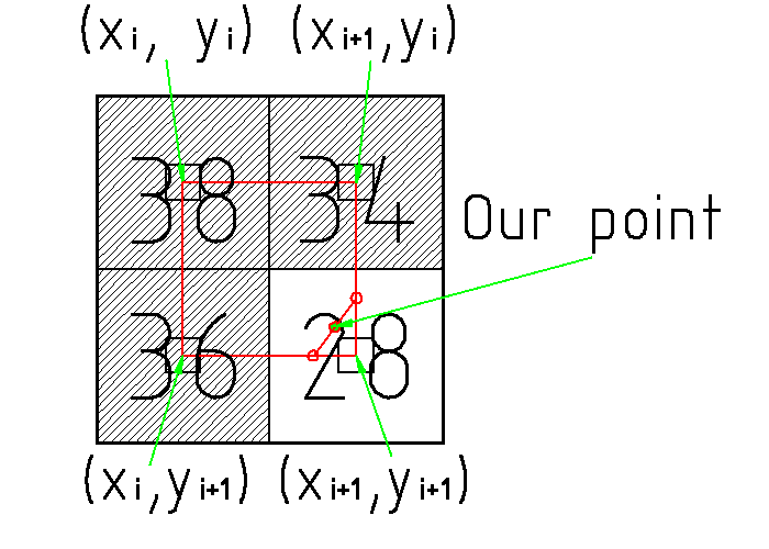
So, let the image have the intensities shown in the figure (numbers inside the cells). We perform isophotes at level 30. The configuration of pixel neighbors (x i , y i ) corresponds to a mask value of seven. We call the corresponding function, which by linear interpolation calculates the coordinates of the contour reference points on the straight lines connecting the right two pixels along the vertical and the bottom two along the horizontal. Corresponding dots are marked with open red circles. Combining them with a straight line and finding its center, we obtain the desired isophote site (marked with a red circle with a green fill, “Our point”). This, of course, is not a very correct method, but for most tasks it is sufficient. Each node is added to the tail of the corresponding list.
After the corresponding mask value is used, it is reset and we move to the next adjacent pixel of the mask. If its contents correspond to the next isophote site, we continue the calculation, otherwise, we “close” the isophote. Immediately after the “closure” of the isophotes, we check, firstly, whether it is too short (say, around a single pixel), and second, we check its closeness: if the beginning and end of the isophotes lie no further than, say, , 2 pixels apart, we consider it closed.
The “closing” of the isophotes is that “just in case” it is checked whether the isophote continues from its first point in the opposite direction. To do this, we go to the bottom of the first pixel of the mask with the prohibition of the movement "up". If we find a continuation of the isophotes there, then we go right through to its completion, adding nodes to the head of the list and choosing counterclockwise priorities.
All of the above is true until we “stumble” on special pixels: 6 and 9. Two isophotes pass through these pixels of the mask, so it is necessary to choose the right next direction based on the “forbidden” direction. So, for example, if we “stumble” on the value of 6, coming to the left, the next direction will be “up”.
In order to “not forget” about another point of the contour at the next pass, we replace the special value with “not special”, simply “paint over” the already used pixel (i.e., for example, for the case of hitting the “six” on the left, we “ paint over the top left pixel, i.e. replace 6 by 7). This method, unfortunately, causes a “slip” in the case of single-pixel “dips” in the “humps” of intensity. But, unfortunately, fixing this is a very difficult algorithmic task that will take too much machine time to build isophotes. And for most images, the described method works fine.
Thus, the "special" pixels are used twice, resetting only after the second pass. The calculation of nodes at specific points is the opposite: for this, a function is taken with the “painting” the opposite pixel to be used.
')
I will illustrate the work of the algorithm on the example of the two-pixel “peak” bypass, shown in the figure below.
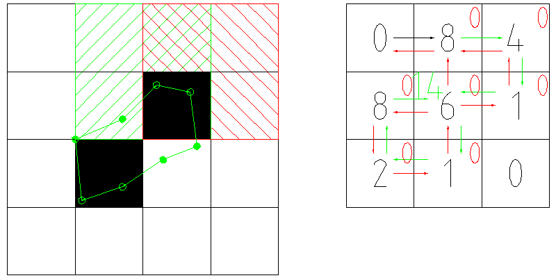
A reduced 4x4 pixel image corresponds to a 3x3 pixel mask (right). We start the motion with the upper left pixel of the image. Because on the mask, it corresponds to zero, we go to the adjacent right pixel of the mask (remember that we have a "ban" on the direction "to the right"). Forbidden directions are shown in fig. right red arrows, “empty” transitions - black arrow transitions with the calculation of the nodes of the isolines - green arrows.
So, we “stumble” onto the figure-eight and, using the appropriate function, calculate the position of the first isophote site. Next, we look into a previously prepared array and see that the directions of the "descent" from the current pixel are either "right" or "down." We choose the direction “right” and go to the next pixel (4), not forgetting to reset the mask pixel already used (zeroing of the pixels is marked with red zeros in the upper right corner of the pixel).
Then we go to the value 1, and after it to the singular point with the value 6. Since we came to the right, then the node value is calculated by the function for the mask value of seven, and the six on the mask is replaced with 14. Then go down to one.
After we go through one, two and eight, we will return to our “special” pixel, but there will already be a value of 14, i.e. further calculation will occur “as if nothing had happened”, after which we will have to move upwards. However, at the top we stumble on zero. We cannot add anything to the “head” of the list of nodes either, since the value below the initial pixel of the isoline is also reset. Therefore, we check the proximity of the start and end nodes of the line. They are pretty close, and we can mark this isoline as closed.
All source code for the algorithm can be found here . I also plan to add parallelization of the computation of isolines of different levels in order to run at least 4..8 parallel streams. So far, in one stream, for a test image of 3000x3000 pixels, the construction of isophots by 16 levels takes about 1.2s.
The first implementation (by the way, quite fast) was unsuccessful: I built a mask common to all levels, and for a particular level I recalculated separately, at the points through which several contour lines pass, we get gaps. Picking tricks on the code led to more and more interlocks and flags, so I decided to go to the detriment of performance and calculate the masks separately for each intensity level.
So, briefly, I will repeat what the “walking squares” method is. To construct isophotes of level I i , a special mask is first constructed: for each pixel of the image, the relative position of the “neighbors” is coded on the right, bottom and bottom right. You can encode it differently, I just presented the code as a 000abcd bit mask, where a, b, c and d are the relative intensities in the corresponding pixels (a is our current image pixel)
If the value in the pixel is greater than the level of the isoline, a unit is assigned to the corresponding bit, otherwise - zero. If w is the width of the image, and * in is a pointer to pixel a, then the mask value (* out) for this pixel is calculated as follows:
*out = (unsigned char) ((in[0]>lvl)<<3) | ((in[1]>lvl)<<2) | ((in[w]>lvl)<<1) | (in[w+1]>lvl); As a result, depending on the configuration of the pixels, we get one of 16 values:
The mask size is one less in both dimensions than the image size.
The next step is the sequential testing of all mask pixels for inequality of zero and 15. As soon as we find such a pixel, we begin to build an isoline from it. In order to build contour lines correctly, we need to memorize the direction from which we approached this pixel. In the figure above, the arrows indicate the possible paths of “derailment” from each pixel of the mask. If we do not take into account the forbidden direction (from which we came), we will either have to check the extra mask pixels, or else (in the case of special points 6 and 9, but about them a little later) we may in general incorrectly choose the position of the next isophotes.
As the mask pixels are viewed (from left to right and from top to bottom, if we consider the origin of the image in the upper left corner), until we find only empty cells, the “forbidden” direction is the “left” direction. As soon as we find a cell containing a section of the isoline, we, in accordance with a previously prepared array of "directions", choose the next direction, cutting off the "forbidden". If there are two such directions, we choose right or down (with priority on “right”) when moving clockwise and left or up (with priority on “up”) when moving counterclockwise (more on that later).
After that, we calculate the position of the contour node for a particular pixel. This is done using one of the array of functions, in accordance with the mask value in this pixel. The figure below explains how this position is calculated.
So, let the image have the intensities shown in the figure (numbers inside the cells). We perform isophotes at level 30. The configuration of pixel neighbors (x i , y i ) corresponds to a mask value of seven. We call the corresponding function, which by linear interpolation calculates the coordinates of the contour reference points on the straight lines connecting the right two pixels along the vertical and the bottom two along the horizontal. Corresponding dots are marked with open red circles. Combining them with a straight line and finding its center, we obtain the desired isophote site (marked with a red circle with a green fill, “Our point”). This, of course, is not a very correct method, but for most tasks it is sufficient. Each node is added to the tail of the corresponding list.
After the corresponding mask value is used, it is reset and we move to the next adjacent pixel of the mask. If its contents correspond to the next isophote site, we continue the calculation, otherwise, we “close” the isophote. Immediately after the “closure” of the isophotes, we check, firstly, whether it is too short (say, around a single pixel), and second, we check its closeness: if the beginning and end of the isophotes lie no further than, say, , 2 pixels apart, we consider it closed.
The “closing” of the isophotes is that “just in case” it is checked whether the isophote continues from its first point in the opposite direction. To do this, we go to the bottom of the first pixel of the mask with the prohibition of the movement "up". If we find a continuation of the isophotes there, then we go right through to its completion, adding nodes to the head of the list and choosing counterclockwise priorities.
All of the above is true until we “stumble” on special pixels: 6 and 9. Two isophotes pass through these pixels of the mask, so it is necessary to choose the right next direction based on the “forbidden” direction. So, for example, if we “stumble” on the value of 6, coming to the left, the next direction will be “up”.
In order to “not forget” about another point of the contour at the next pass, we replace the special value with “not special”, simply “paint over” the already used pixel (i.e., for example, for the case of hitting the “six” on the left, we “ paint over the top left pixel, i.e. replace 6 by 7). This method, unfortunately, causes a “slip” in the case of single-pixel “dips” in the “humps” of intensity. But, unfortunately, fixing this is a very difficult algorithmic task that will take too much machine time to build isophotes. And for most images, the described method works fine.
Thus, the "special" pixels are used twice, resetting only after the second pass. The calculation of nodes at specific points is the opposite: for this, a function is taken with the “painting” the opposite pixel to be used.
')
I will illustrate the work of the algorithm on the example of the two-pixel “peak” bypass, shown in the figure below.
A reduced 4x4 pixel image corresponds to a 3x3 pixel mask (right). We start the motion with the upper left pixel of the image. Because on the mask, it corresponds to zero, we go to the adjacent right pixel of the mask (remember that we have a "ban" on the direction "to the right"). Forbidden directions are shown in fig. right red arrows, “empty” transitions - black arrow transitions with the calculation of the nodes of the isolines - green arrows.
So, we “stumble” onto the figure-eight and, using the appropriate function, calculate the position of the first isophote site. Next, we look into a previously prepared array and see that the directions of the "descent" from the current pixel are either "right" or "down." We choose the direction “right” and go to the next pixel (4), not forgetting to reset the mask pixel already used (zeroing of the pixels is marked with red zeros in the upper right corner of the pixel).
Then we go to the value 1, and after it to the singular point with the value 6. Since we came to the right, then the node value is calculated by the function for the mask value of seven, and the six on the mask is replaced with 14. Then go down to one.
After we go through one, two and eight, we will return to our “special” pixel, but there will already be a value of 14, i.e. further calculation will occur “as if nothing had happened”, after which we will have to move upwards. However, at the top we stumble on zero. We cannot add anything to the “head” of the list of nodes either, since the value below the initial pixel of the isoline is also reset. Therefore, we check the proximity of the start and end nodes of the line. They are pretty close, and we can mark this isoline as closed.
All source code for the algorithm can be found here . I also plan to add parallelization of the computation of isolines of different levels in order to run at least 4..8 parallel streams. So far, in one stream, for a test image of 3000x3000 pixels, the construction of isophots by 16 levels takes about 1.2s.
Source: https://habr.com/ru/post/137028/
All Articles