MSP430 Lunchpad Review and Test Project
Recently, thanks to user Dooez , I ordered a low-cost kit for playing on cold winter evenings on TI.
Literally a few days later, a “courier with a thick shoulder bag ...” and a wonderful FedEx box courier knocked me:
The contents of the box did not disappoint me either. Inside was a smaller box
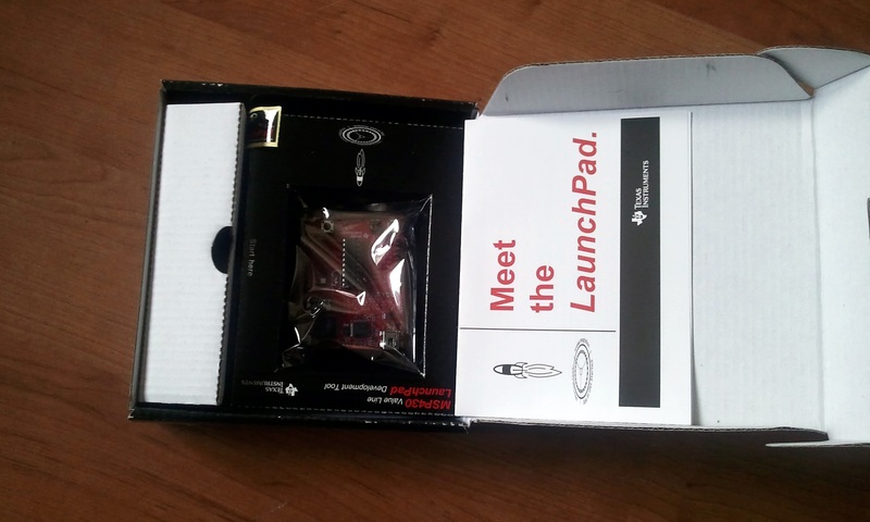
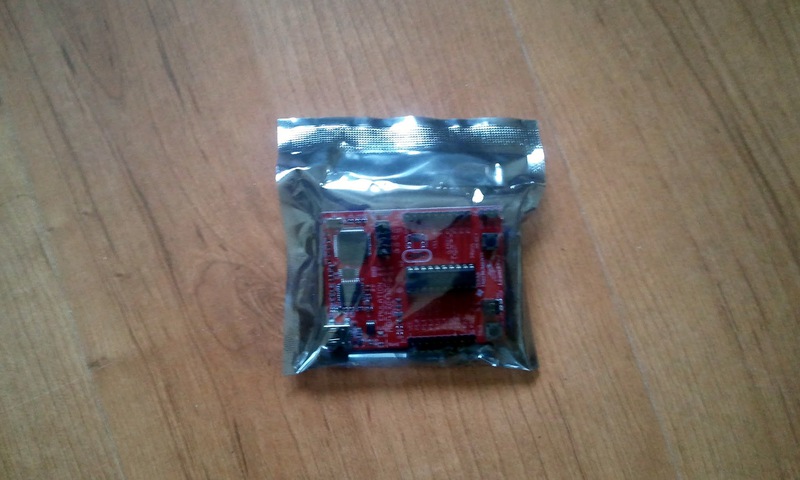
from which the lunchpad board itself was sequentially extracted:
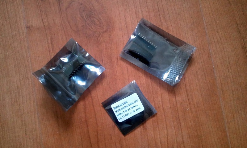
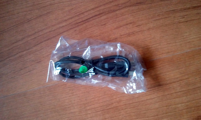
sealed bags with another processor, connectors for the board and quartz at 32 kHz:
short miniUSB
and, as a bonus, a couple of stickers
First of all, of course, unpack the board and the cord and stick it into the comp. Winda happily offers to look for drivers and, of course, does not find anything. Not scary. Downloading pirated IAR Embedded WorkBench from torrents (of course, you could get a trial version from the TI website, but followers of the church of copyism do not look for easy ways), and after installing a programmer / debugger and a virtual COM port in the system.
Initially, a demo program is flashed into the processor, flashing the LED depending on the temperature (yes, percent with all its simplicity can measure its temperature), which we immediately wipe with our simple “flash LED” program, “Hello, World!” for embeds.
I would especially like to mention the possibility of downloading from TI site an archive with a couple of hundreds of tiny (literally a dozen lines) programs in C and Assembler, which demonstrate the features of the microprocessor. As soon as something did not work out - I simply loaded the corresponding example into the processor, and in a few minutes I found the essence of the problem in the debager.
By the way, debager. Great thing! Brekpointy can be put both on the command and on the fulfillment of any condition, plus the possibility, having stopped the processor, to change the bits in the service registers and immediately receive a response in the hardware on the board. Or vice versa, look directly in the registers of the processor response to the applied external influence.
Having played enough, the thought arose to make something useful. And the catcher, as you know, and the beast runs.
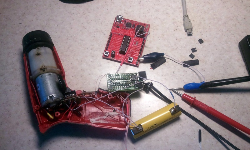
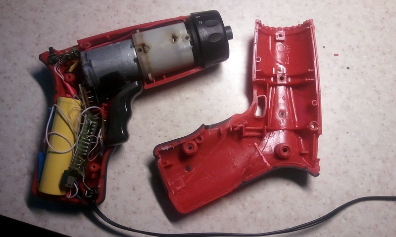
In this old oak Chinese electric screwdriver, the batteries had just died by this time. And the new iron-phosphate accumulators bought on the occasion were lying in store, which all hands did not reach:

The main plus of the 430 series (according to TI) is in ultra-low power consumption. The processor simply asks for some self-powered device. So try to make a screwdriver controller instead of Chinese junk.
So, crush the screwdriver and ruthlessly throw out its dull contents:
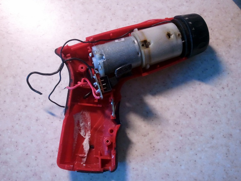
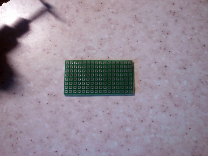
and check that the battery is great (if you break a couple of partitions) and there is still room for a small controller scarf:
He pretends to be on the knee an approximate diagram of the internal electronics of those parts that roll on all sorts of boxes and bags (by the way, because criticism of the selection of components is not accepted, it is soldered from the existing house, I didn’t want to go to the radio market)
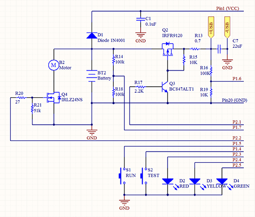
A little explanation to the diagram: USB port is used for charging. It can produce 500 mA at 5 volts, on the battery of this type, the cut-off voltage should be 3.6 volts (3.3V working), we are laying on the charge current of 100 mA when the 1.4V key drops, i.e. To the key resistance we add another small current-limiting resistor. Q2, Q3 are needed precisely for the cut-off when the battery is fully charged. Plus, the same cutoff is triggered by overheating.
Q4 controls the motor (switching directions there is done mechanically, so I did not have to bother with the full bridge), it is more powerful, because motor at start takes up to 3A from battery.
D1 reduces the microprocessor supply voltage to acceptable values.
R14, R18 measure the voltage on the battery, R16 and R19 measure the input voltage.
S1 - a large button on the screwdriver, including the motor. S2 and D2-D4 - a tiny scarf (yes, I did not throw out all the Chinese junk) with a button and three LEDs, red, yellow and green, indicating the charge of the battery.
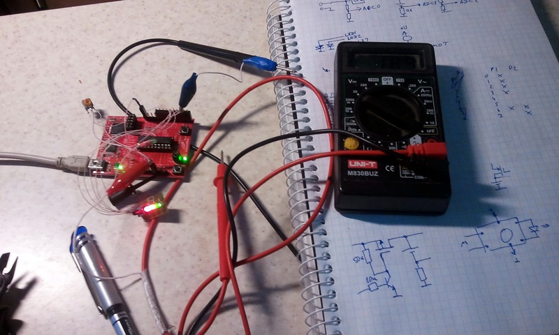
First, I connect a variable resistor to the LanchPad legs, which represents a battery, and a board with indicators. The motor and key represent the LEDs on the board:
I achieve on the mock up more or less confident work of all the pieces of the program and proceed to the assembly of the final board. First we check the geometric dimensions after installing the keys:
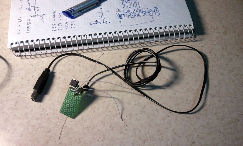
Normally, fit in size, you can solder a spare microprocessor, hang on it the necessary SMD components and make all the connections using a thin MGTF:

(Yes, in this picture there is an assembled board with all the soldered parts. The wire in red shrink - connect the programmer to the processor, then it will be removed)
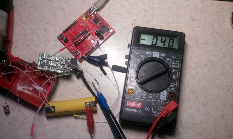
Now from the blinking LEDs go to the torsion of the motor. Lunchpad turns into a programmer with a slight movement of the hand, and the variable resistor temporarily migrates to the finished board in order to check the critical limits of the battery without torturing the battery itself:
Along the way, we check different sleep modes for the processor. Even with fully included power saving, our result is one and a half orders of magnitude higher than what was stated in the documentation, which is not surprising given the resistor dividers for the ADC and the Q2 control circuit. However, 40 microamps is a perfectly acceptable result for several ampere-hours of a battery. For a dozen years on a single charge, the processor will work exactly, and there either the shah will die, or the donkey:
All right, the LEDs flash as expected, the voltage is measured, overheating (simulated by a hair dryer) cuts off the load, charging when plugged into USB turns on - you can collect.
Carefully shove the stuffing inside the case
and twist both halves

now you can, with a clear conscience, upload your source code to a public repository, because the main commandment of copyism fans is “Information must be free!”. Who is interested in the project - you can download the latest version of the source code and altiumovskuyu scheme from here .
There, of course, combing and combing - in the software there are still tails left from the original version of the program with FSM, later I abandoned it in favor of sleep-modes, and the numbering of the elements in the diagram is slightly strange after running in the simulator and erasing unnecessary parts .
')
How to improve the scheme: well, at least instead of a wire, use a miniUSB mom in the case of a screwdriver, because the dangling wire is not Feng Shui.
Another option for aesthetes: after Q2, an inductance and a Schottky diode is installed according to the pulse-step-down converter circuit, then the microprocessor with the help of PWM can charge the battery from any input voltage.
The serial port remained unused on the microprocessor - it is quite possible (using a CP2102 or FTDI converter) to tell the computer battery charge-discharge statistics.
The construction itself will then be used as a basis for tourist battery charging for mobile phones / lamps for overnight stays, which can be charged from Peltye, solar batteries and dynamos. But this is a topic for the next article on Habr.
PS: But generally speaking, this is just a brain break - what would I think if I was told 20 years ago that I would sit at the computer and program a screwdriver ? Another ten years, and learn how to hack toothpicks.
Literally a few days later, a “courier with a thick shoulder bag ...” and a wonderful FedEx box courier knocked me:
The contents of the box did not disappoint me either. Inside was a smaller box
from which the lunchpad board itself was sequentially extracted:
sealed bags with another processor, connectors for the board and quartz at 32 kHz:
short miniUSB
and, as a bonus, a couple of stickers
First of all, of course, unpack the board and the cord and stick it into the comp. Winda happily offers to look for drivers and, of course, does not find anything. Not scary. Downloading pirated IAR Embedded WorkBench from torrents (of course, you could get a trial version from the TI website, but followers of the church of copyism do not look for easy ways), and after installing a programmer / debugger and a virtual COM port in the system.
Initially, a demo program is flashed into the processor, flashing the LED depending on the temperature (yes, percent with all its simplicity can measure its temperature), which we immediately wipe with our simple “flash LED” program, “Hello, World!” for embeds.
I would especially like to mention the possibility of downloading from TI site an archive with a couple of hundreds of tiny (literally a dozen lines) programs in C and Assembler, which demonstrate the features of the microprocessor. As soon as something did not work out - I simply loaded the corresponding example into the processor, and in a few minutes I found the essence of the problem in the debager.
By the way, debager. Great thing! Brekpointy can be put both on the command and on the fulfillment of any condition, plus the possibility, having stopped the processor, to change the bits in the service registers and immediately receive a response in the hardware on the board. Or vice versa, look directly in the registers of the processor response to the applied external influence.
Having played enough, the thought arose to make something useful. And the catcher, as you know, and the beast runs.
In this old oak Chinese electric screwdriver, the batteries had just died by this time. And the new iron-phosphate accumulators bought on the occasion were lying in store, which all hands did not reach:
The main plus of the 430 series (according to TI) is in ultra-low power consumption. The processor simply asks for some self-powered device. So try to make a screwdriver controller instead of Chinese junk.
So, crush the screwdriver and ruthlessly throw out its dull contents:
and check that the battery is great (if you break a couple of partitions) and there is still room for a small controller scarf:
He pretends to be on the knee an approximate diagram of the internal electronics of those parts that roll on all sorts of boxes and bags (by the way, because criticism of the selection of components is not accepted, it is soldered from the existing house, I didn’t want to go to the radio market)
A little explanation to the diagram: USB port is used for charging. It can produce 500 mA at 5 volts, on the battery of this type, the cut-off voltage should be 3.6 volts (3.3V working), we are laying on the charge current of 100 mA when the 1.4V key drops, i.e. To the key resistance we add another small current-limiting resistor. Q2, Q3 are needed precisely for the cut-off when the battery is fully charged. Plus, the same cutoff is triggered by overheating.
Q4 controls the motor (switching directions there is done mechanically, so I did not have to bother with the full bridge), it is more powerful, because motor at start takes up to 3A from battery.
D1 reduces the microprocessor supply voltage to acceptable values.
R14, R18 measure the voltage on the battery, R16 and R19 measure the input voltage.
S1 - a large button on the screwdriver, including the motor. S2 and D2-D4 - a tiny scarf (yes, I did not throw out all the Chinese junk) with a button and three LEDs, red, yellow and green, indicating the charge of the battery.
First, I connect a variable resistor to the LanchPad legs, which represents a battery, and a board with indicators. The motor and key represent the LEDs on the board:
I achieve on the mock up more or less confident work of all the pieces of the program and proceed to the assembly of the final board. First we check the geometric dimensions after installing the keys:
Normally, fit in size, you can solder a spare microprocessor, hang on it the necessary SMD components and make all the connections using a thin MGTF:
(Yes, in this picture there is an assembled board with all the soldered parts. The wire in red shrink - connect the programmer to the processor, then it will be removed)
Now from the blinking LEDs go to the torsion of the motor. Lunchpad turns into a programmer with a slight movement of the hand, and the variable resistor temporarily migrates to the finished board in order to check the critical limits of the battery without torturing the battery itself:
Along the way, we check different sleep modes for the processor. Even with fully included power saving, our result is one and a half orders of magnitude higher than what was stated in the documentation, which is not surprising given the resistor dividers for the ADC and the Q2 control circuit. However, 40 microamps is a perfectly acceptable result for several ampere-hours of a battery. For a dozen years on a single charge, the processor will work exactly, and there either the shah will die, or the donkey:
All right, the LEDs flash as expected, the voltage is measured, overheating (simulated by a hair dryer) cuts off the load, charging when plugged into USB turns on - you can collect.
Carefully shove the stuffing inside the case
and twist both halves
now you can, with a clear conscience, upload your source code to a public repository, because the main commandment of copyism fans is “Information must be free!”. Who is interested in the project - you can download the latest version of the source code and altiumovskuyu scheme from here .
There, of course, combing and combing - in the software there are still tails left from the original version of the program with FSM, later I abandoned it in favor of sleep-modes, and the numbering of the elements in the diagram is slightly strange after running in the simulator and erasing unnecessary parts .
')
How to improve the scheme: well, at least instead of a wire, use a miniUSB mom in the case of a screwdriver, because the dangling wire is not Feng Shui.
Another option for aesthetes: after Q2, an inductance and a Schottky diode is installed according to the pulse-step-down converter circuit, then the microprocessor with the help of PWM can charge the battery from any input voltage.
The serial port remained unused on the microprocessor - it is quite possible (using a CP2102 or FTDI converter) to tell the computer battery charge-discharge statistics.
The construction itself will then be used as a basis for tourist battery charging for mobile phones / lamps for overnight stays, which can be charged from Peltye, solar batteries and dynamos. But this is a topic for the next article on Habr.
PS: But generally speaking, this is just a brain break - what would I think if I was told 20 years ago that I would sit at the computer and program a screwdriver ? Another ten years, and learn how to hack toothpicks.
Source: https://habr.com/ru/post/136219/
All Articles