The interaction of the circuit in Proteus with the outside world
Introduction
I think many of those who are somehow connected with the development of electronic devices have heard at least once about the Proteus software package from Labcenter Electronics. Whatever the extensive library of components available for modeling, the "life" of the circuit is limited to the emulator window, with rare exceptions. There are already several models that I can, for example, write some data to a file or even be presented to the system as USB devices, but for now they can solve a small class of problems.
Task
When working on a course project, in which it is necessary to develop a system for radio control of the aircraft, it became necessary to connect the model with a PC. Since one of the simplest interfaces for communication with a PC is RS-232 , it was chosen (the usb-uart adapter was used).
So how to debug this system at the very beginning, when quite serious errors have not yet been found that can lead to failure of electronic components, and not to bother with frequent firmware microcontroller (s)?
Quite a convenient solution is Proteus. But then a new problem appears - connection with the PC.
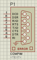 The component library contains the COMPIM model, which allows you to connect a circuit to a PC's COM port, which allows you to process requests coming from devices connected to this COM port as if they were connected to an emulated device. You can of course through another COM port connect to the one that is connected to the circuit, but this requires 2x COM ports and an external null modem cable.
')
Immediately comes to mind the idea of virtual com ports. For example, com0com , which creates 2 virtual COM ports, the input and output of which is redirected into each other. And for those who for some reason are working on virtual machines, it may be useful to redirect com ports with VM tools.
But
Steps to create a model
Creating a graphic image of the model
Add a rectangle, another rectangle, text, conclusions (using Device Pins), we get:

described in detail in that article or here
Program development
To interact with the model, I decided to use the named pipes of Windows. Perhaps the solution will seem strange, but the idea is to provide the interface as close as possible to the interface of the real device. The choice fell on named pipes, since working with them and COM ports is almost identical to working with regular files.
But even if we have a communication channel with the "outside world", then how to implement the exchange on the uart interface?
We need to remember its frame format:
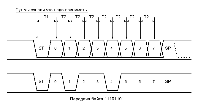
The logic of generating / parsing a signal of this type is allocated to a separate class.
The main for the proteus model will be two methods:
making the initial setup:
VOID PIPEUARTMODEL::setup (IINSTANCE *instance, IDSIMCKT *dsimckt) { uart = new Uart(); logger = new Logger(instance); pipe = new Pipe("\\\\.\\pipe\\uart", logger); // dsimckt ckt = dsimckt; // txd = instance->getdsimpin("TXD", true); rxd = instance->getdsimpin("RXD", true); // txd txd->setstate(SHI); // 2 ckt->setcallback(1, this, rxd_event); ckt->setcallback(2, this, txd_event); } and that jerked by callback
VOID PIPEUARTMODEL::callback(ABSTIME time, EVENTID eventid) { switch (eventid) { case rxd_event: uart->rxBit(ishigh(rxd_pin_state)); // if (uart->rxC) { pipe->rxd_queue.push(uart->rxD); // pipe uart->rxC = 0; } // ckt->setcallback(time + 1000000000000 / uart_baudrate, this, rxd_event); break; case txd_event: if ((uart->txC) && (!pipe->txd_queue.empty())) { uart->txD = pipe->txd_queue.front(); // uart pipe->txd_queue.pop(); } txd->setstate(time, 1, uart->txBit() ? SHI : SLO); // ckt->setcallback(time + 1000000000000 / uart_baudrate, this, txd_event); break; } } Testing
An example of how my model works with Virtual Terminal:
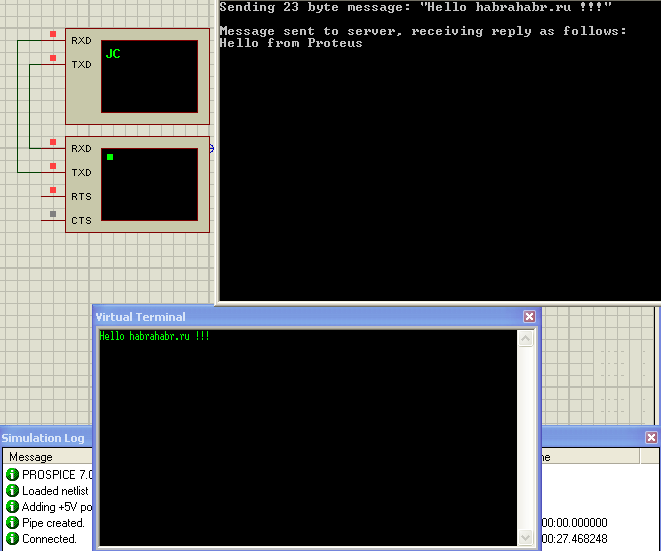
There is still to check how convenient this solution will be, but at first glance, it completely suits me.
I hope the presented recipes will help solve many of your problems.
List of sources
Source: https://habr.com/ru/post/135914/
All Articles