Radio-controlled Wi-Fi machine with a camera
Start
In the summer, there was an idea to make a radio-controlled machine, but not just something similar to the creation of Chinese engineering, which is sold at every turn, but a machine that could be controlled from a computer or phone. It is understood that the machine, which can be controlled via Wi-Fi in its pure form, is not at all interesting. But what if she had a camera? And if you still control via 3G / EDGE / GPRS? This is another matter! This means that the control device should have USB and Wi-Fi (or just USB, you can buy a USB Wi-Fi adapter). Now you need to figure out how to control the engines. Initially, I wanted to do this with the help of the COM port and the shift register (74HC595), but having burned 5 such chips, I refused this method. Later, my eyes fell on the Arduino, namely on the Arduino Duemilanove. This board has 14 digital I / O ports, six of them are PWM (it will be possible to control the voltage on the motor and hang up the servos for the camera), two can be used as the Tx and Rx serial ports.
Router
Having found the D-Link DIR-320 router in my city, which has a USB port, I immediately bought it. When I got home, I learned that this router has an unmarked UART port. Thus, we have a communication channel between the router and arduina.
For the router, I chose the OpenWrt firmware. You can download the finished firmware from OpenWrt for DIR-320 is here . I do not remember why already, but I decided to assemble the firmware myself (described in detail here ). This will require Linux (I built on Ubuntu 11.10). First, download the firmware sources and collect everything you need:
svn co svn://svn.openwrt.org/openwrt/branches/backfire dir320 cd dir320 ./scripts/feeds update -a && ./scripts/feeds install –a make prereq && make tools/install && make toolchain/install Configuring the firmware
make menuconfig Choose the following packages:
- Target System ---> <*> Broadcom BCM947xx / 953xx - 2.6 kernel
- Image configuration ---> <*> LAN IP Address ---> <IP address> - [optional] You can select the IP address that the router will have after booting the kernel and all modules
- Kernel modules ---> <*> Filesystems ---> <*> kmod-fs-ext3 - more on this later
- Utilities ---> Filesystem ---> <*> e2fsprogs - And about that
- Utilities ---> disc ---> <*> block-extroot - And that too
- Kernel modules ---> <*> USB Support ---> <*> kmod-usb-core - USB support
- Kernel modules ---> <*> USB Support ---> <*> kmod-usb-ohci - for USB hub. Why is he? More about this later
- Kernel modules ---> <*> USB Support ---> <*> kmod-usb-storage - USB flash drive support
- Kernel modules ---> <*> USB Support ---> <*> kmod-usb2 - USB 2.0
- Administration -> webif ---> <*> webif-applications - admin panel
- Kernel modules ---> <*> Video Support ---> <*> kmod-usb-video-core - USB-video support
- Kernel modules ---> <*> Video Support ---> <*> kmod-usb-video-uvc - support for UVC-webcams
Choose the last item, I had a UVC webcam.
So why did we choose those packages, the purpose of which I did not explain? The problem is that the amount of flash memory installed in the router is 4MB, which can interfere with our further work. We will transfer rootfs to a USB flash drive, and the router will boot from it.
By the way, about flash memory: you need not forget the following:
make kernel_menuconfig- Device Drivers ---> <*> Memory Technology Device (MTD) support ---> RAM / ROM / Flash chip drivers ---> [*] Flash chip driver advanced configuration options -> [*] Specific CFI Flash geometry selection -> [*] Support 8-bit buswidth
- Device Drivers ---> <*> Memory Technology Device (MTD) support ---> RAM / ROM / Flash chip drivers ---> [*] Flash chip driver advanced configuration options -> [*] Specific CFI Flash geometry selection -> [*] Support 16-bit buswidth
And in Kernel Hacking, you need to fix
console=/dev/ttyS0 on console=/dev/null so that the router does not use this port as a debugging one.Compile and flash
Compile the firmware:
make V=99 -j2 Now you need to flash it:
For bash:
#!/bin/bash echo "==================================================================" echo "This script will upload dd-wrt firmware (firmware.bin)" echo "in the current directory to 192.168.0.1 " echo "during the router's bootup. " echo "" echo "* Set your ethernet card's settings to: " echo " IP: 192.168.0.10 " echo " Mask: 255.255.255.0 " echo " Gateway: 192.168.0.1 " echo "* Unplug the router's power cable. " echo "" echo "Press Ctrl+C to abort or any other key to continue... " read echo "" echo "* Re-plug the router's power cable. " echo "" echo "==================================================================" echo "Waiting for the router... Press Ctrl+C to abort. " echo "" try(){ ping -c 1 -w 1 192.168.0.1 } try while [ "$?" != "0" ] ; do try done echo "*** Start Flashing **** " atftp --no-source-port-checking -p -l firmware.bin 192.168.0.1 echo "Firmware successfully loaded!" For Windows:
@echo off echo ================================================================== echo This batch file will upload dd-wrt firmware in the current directory to echo 192.168.0.1 during the router's bootup. echo. echo * Set your ethernet card's settings to: echo IP: 192.168.0.2 echo Mask: 255.255.255.0 echo Gateway: 192.168.0.1 echo * Unplug the router's power cable. echo. echo Press Ctrl+C to abort or any other key to continue... pause > nul echo. echo * Re-plug the router's power cable. echo. echo ================================================================== echo Waiting for the router... Press Ctrl+C to abort. echo. set FIND=%WINDIR%\command\find.exe if exist %FIND% goto LPING set FIND=%WINDIR%\system32\find.exe if exist %FIND% goto LPING set FIND=find :LPING ping -n 1 -w 50 192.168.0.1 | %FIND% "TTL=" if errorlevel 1 goto LPING echo *** Start Flashing **** tftp -i 192.168.0.1 put firmware.bin if errorlevel 1 goto LPING set FIND= echo. echo ================================================================== echo * WAIT for about 2 minutes while the firmware is being flashed. echo * Reset your ethernet card's settings back to DHCP. echo * The default router address will be at 192.168.1.1 echo. Pause Configuring boot from flash drive
After the first power up, go to the web interface of the router and change the password. Now connect to it via SSH. You need to configure the boot from the flash drive, for this you first need to mark it. I had two sections: the first is an ext3 partition for rootfs, the second is a swap. Open / etc / config / fstab in vim and write what corresponds to our felshka. I have so:
config global automount option from_fstab 1 option anon_mount 1 config global autoswap option from_fstab 1 option anon_swap 0 config mount option target / option device /dev/sda1 option fstype ext3 option options rw,sync option enabled 1 option enabled_fsck 1 option is_rootfs 1 config swap option device /dev/sda2 option enabled 1 Save, reboot.
Demon
Arduin will control the engines, so we will write a daemon that will redirect everything that came to TCP port 5554 on / dev / ttyS0.
Search for my compiled version of the daemon in the archive (card)
Compile with gcc, which was compiled in preparation for the firmware build:
<…>/dir320/staging_dir/toolchain-mipsel_gcc-4.3.3+cs_uClibc-0.9.30.1/usr/bin/mipsel-openwrt-linux-uclibc-gcc-4.3.3 < > -o < > A small digression about the convenience of organizing work with the router
- After each power up, I had to write
opkg update, so I added it to /etc/rc.local - It is quite convenient to use an FTP server. I put pure-ftpd. To do this, we write:
opkg install pure-ftpd
Add it to /etc/rc.local:pure-ftpd -4 –B –M –l unix –U 000:000 - It will be convenient to change the web interface to luci, for this we write:
opkg remove webif* opkg install luci
Demon [continued]
Fill our daemon on the router, add it to autoload.
Now put mjpg-streamer:
opkg install mjpg-streamer We write the following to / etc / config / mjpg-stramer:
config mjpg-streamer option device “/dev/video0” option resolution “640x480” option fps “24” option port “8080” option enabled “true” We try to connect the camera. If everything is fine, then you can see the image here:
http: // <router IP> /? action = stream .
Arduino and compound
To begin with we will be defined with the scheme of connection of engines. Since I took the case from the already finished typewriter, I was lucky with the engines - they were already there. The front one was in charge of turns (left, right, straight), and the rear one was in motion (I had to change the button for locking the doors of some VAZ to the engine). Arduine loads can be controlled using field-effect transistors (95N2LH5, but I used the IRF 630, because I found these fir trees in my city). Connection is: the earth of the transistor - to the control pin of the arduin, source - to the ground of the arduin and the minus of the supply voltage, drain - to the minus of the load, plus the power supply to the plus of the load. But in this way we can only go forward and turn only in one direction. In order to cope with the problem, a relay with two groups of contacts hurries to our aid. I had one engine (front) powered by 6 volts, and the other 12. This used two 6 volt batteries (one of them is a lead-acid battery from a back-up), given that the minus of the router would later have to be connected to the arduin ground, then get 6 volts for a router it does not work out (check how many volts you apply to the router - I had to buy one more after I gave it 12 volts). So I had to use another relyushku to supply / non-supply power to the front engine.
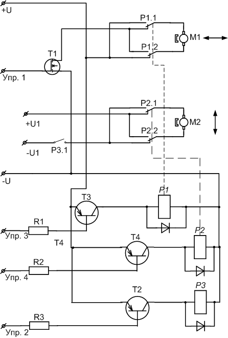
Scheme painted for a long time. Now there are all field effect transistors and no resistors.
Now about the code itself. Everything is pretty simple for me - there are 4 commands that have their own parameter with a size of 1 byte:
- m - Responsible for voltage, and, therefore, for speed, on the engine a value from 0 to 255
- r - Responsible for turns. “1” - turn, “0” - do not turn
- n - “1” - go backwards, “0” - go forward
- e - “1” - turn in the other direction
Here is my program code for arduine:
int inByte, val; void setup() { Serial.begin(9600); pinMode(2, OUTPUT); pinMode(4, OUTPUT); pinMode(7, OUTPUT); } void loop() { if (Serial.available() > 0) { inByte = Serial.read(); if ((inByte=='n')||(inByte=='e')){ while (Serial.available()==0) {} val=Serial.read(); if (inByte=='n'){ if (val=='1'){ digitalWrite(2, HIGH); Serial.print("Writing to 2 pin\n\r"); } if (val=='0'){ digitalWrite(2, 0); Serial.print("Writing to 2 pin\n\r"); } } if (inByte=='e'){ if (val=='1'){ digitalWrite(4, HIGH); Serial.print("Writing to 4 pin\n\r"); } if (val=='0'){ digitalWrite(4, LOW); Serial.print("Writing to 4 pin\n\r"); } } } if ((inByte=='m')||(inByte=='r')){ while (Serial.available()==0) {} val=Serial.read(); if (inByte=='m'){ if (val!='0') analogWrite(3, val); else analogWrite(3, 0); Serial.print("Writing to 3 pin\n\r"); } if (inByte=='r'){ if (val=='1'){ digitalWrite(7, HIGH); Serial.print("Writing to 7 pin\n\r"); } if (val=='0'){ digitalWrite(7, LOW); Serial.print("Writing to 7 pin\n\r"); } } } } } As you can see, I have the back motor connected to 3 pins, the front one - to 7, the rear relay - to 2 pins, the front one - to 4. Since 3 is a PWM pin, using analogWrite (3, val) ;, where val from 0 to 255, we can control the voltage on the motor.
We disassemble our router. We see the UART port. We connect it with arduinoy.

Now we look, how it all works. Connect with telnet to our port and check:
- n1 - clicks the relay
- m <space> - the wheels begin to rotate slightly
- n0 - wheels rotate in the other direction
- m0 - wheels stop spinning
- r1 - turn the front wheels
- e1 - wheels turn the other way
- r0 - wheels get straight
- e0 - clicks the relay
You can use minicom (
opkg install minicom ) to debug work with the com port on the router.Software part
In the archive, my program for controlling the machine (rotate and power from the archive must be copied to / bin / on the router, card is my demon). It works only with a joystick. On the scheduling tab, you can write a bash script (don't forget
opkg install bash on the router) to execute it using the cron daemon. Since this daemon needs to be restarted after changing its settings, my program runs the script at http: // <IP address> / cron-restart . Therefore, you need to create it (/ www / cgi-bin / cron-restart) and do not forget to make it executable. Code: #!/bin/bash /etc/init.d/cron stop; /etc/init.d/cron start Conclusion
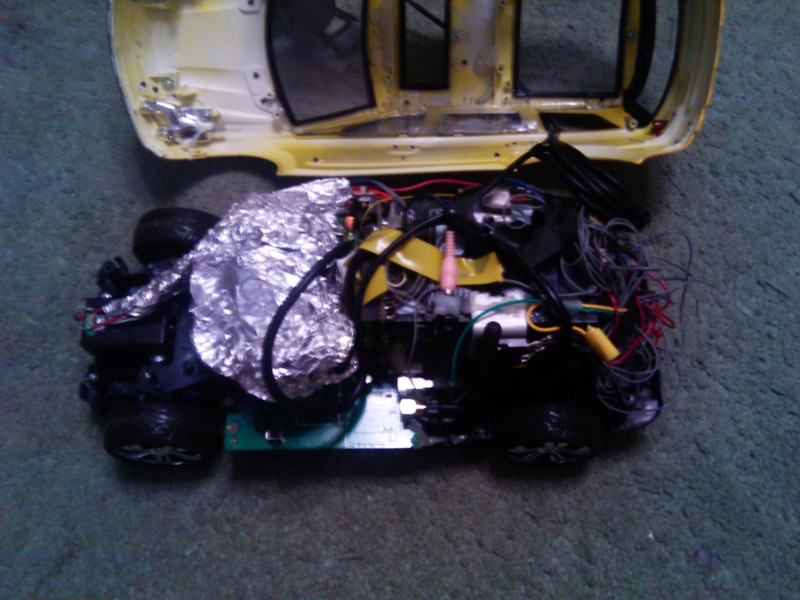
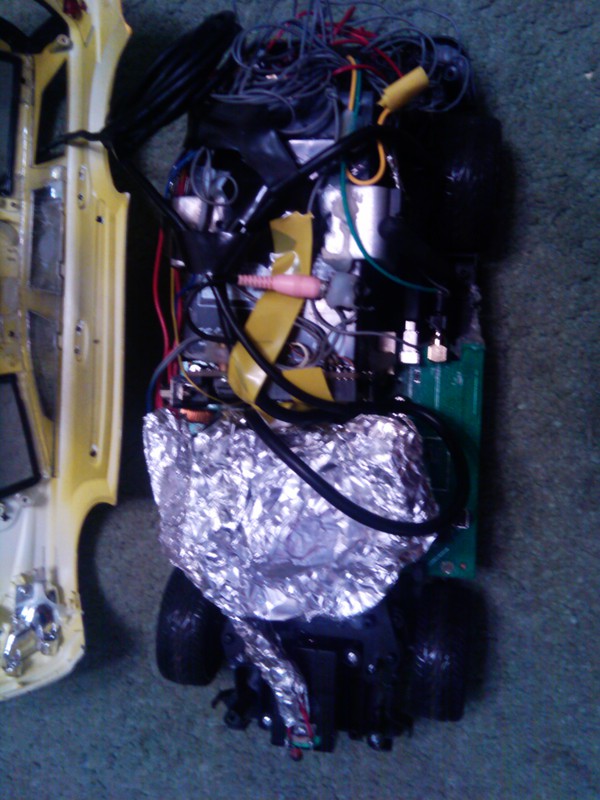
It seems that I have not forgotten anything. Oh, of course! Here is my masterpiece:
')


You can connect Bluetooth to such a device (I have not tried it, but there is a driver), a 3G modem (I managed to get the Internet, but it seems that the provider does not give each client its own external ip address, so you will have to use something like back-connect or vpn), gps receiver (no problems should arise - after all, it should be defined as a serial port).
Notes
If the router suddenly reboots, then it is worth removing all the wires away from it or all of them to shield. Experimentally, I realized that the router can reboot from interference, so I had to wrap the hub with several layers of insulation and aluminum foil.
And more. Instead of a router, you can use Raspberry Pi , and instead of transistors and relays - Arduino Motor Shield.
Archive, which more than once I mentioned ( mirror ).
Source: https://habr.com/ru/post/135790/
All Articles