Lego and Arduino mechanical display
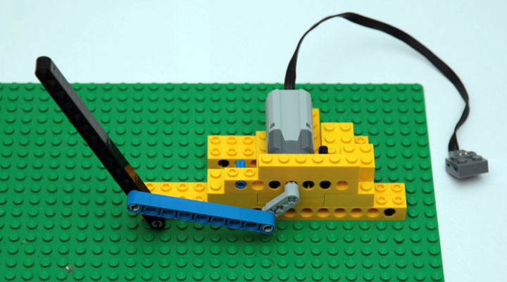
If you believe the textbooks, the first "TVs" were mechanically scanned on the Nipkoff disc . Understandably, the definition of a TV for everyone has its own and for home use mechanics of little use, but I decided to try to make a mechanical display. Fortunately, an eight-year-old specialist in motors showed up in the family, and he made the “hardware” part of the installation. Lego Power Functions Medium Motor, powered by nine volts, is capable of using the crank mechanism to swing the bar into 15 holes with a frequency of several Hertz.
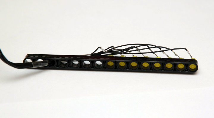
The next step was the installation of LEDs. Fortunately, the diameter of the Lego holes is exactly 5 mm, so that the diodes ideally fit with great effort and do not loosen up during operation. The cathodes connected together, and the anodes brought separately out with a soft wire at 0.05. It turned out nine conductors, but the engine has enough power in abundance.
')
Now we need to take care of synchronization. The engine I have is the simplest - not stepping and without an encoder, so I decided to catch the beginning of the cycle with a photocell. Behind the motor fortified bright LED that shines through a thin tube. The beam of light at each turn intersects the crank and dims the photoresistor. To reduce interference from external lighting, he looks exactly at the LED, also through a straw.
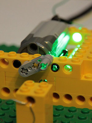
The photoresistor is fixed just by holding it between two Lego dice.

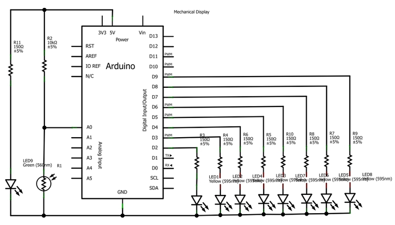
Now it remains to connect the structure to the Arduino. The LEDs connected to the digital outputs through the limiting resistors of 150 Ohms, the photoresistor - to the input of the ADC.
As a result, my "TV" began to look like this:
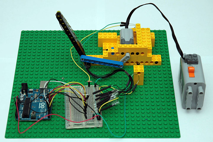
Fill a simple program that waits for the photoresistor to black out, and then fires the required data at the digital outputs (2..9) at a specified interval. The horizontal size of one pixel is determined by the manually selected delay; for my installation, the optimal value was 2.3 milliseconds.
Now, with bated breath, turn on, and here it is, a wonderful moment!

The resolution of the order of 30 pixels horizontally by 8 vertically, with smaller delays, the pixels are too compressed. The frame rate is about five per second.
The idea of using lego was borrowed from the Michael Extreme NXT book by Michael Gasperi. Fortunately, buying Mindstorms NXT for three hundred euros is not necessary, and you can get an order of magnitude cheaper Arduino.
The next step was the installation of LEDs. Fortunately, the diameter of the Lego holes is exactly 5 mm, so that the diodes ideally fit with great effort and do not loosen up during operation. The cathodes connected together, and the anodes brought separately out with a soft wire at 0.05. It turned out nine conductors, but the engine has enough power in abundance.
')
Now we need to take care of synchronization. The engine I have is the simplest - not stepping and without an encoder, so I decided to catch the beginning of the cycle with a photocell. Behind the motor fortified bright LED that shines through a thin tube. The beam of light at each turn intersects the crank and dims the photoresistor. To reduce interference from external lighting, he looks exactly at the LED, also through a straw.
The photoresistor is fixed just by holding it between two Lego dice.
Now it remains to connect the structure to the Arduino. The LEDs connected to the digital outputs through the limiting resistors of 150 Ohms, the photoresistor - to the input of the ADC.
As a result, my "TV" began to look like this:
Fill a simple program that waits for the photoresistor to black out, and then fires the required data at the digital outputs (2..9) at a specified interval. The horizontal size of one pixel is determined by the manually selected delay; for my installation, the optimal value was 2.3 milliseconds.
/* Shows a picture on mechanical desply connected to Arduino Display's LED connected to digital pins 2..9 via 150 Ohm resisitors Photoresistor connected to analog pin 0 and GND. It is also connected to 5V using 10 kOhm resistor. */ void setup() { for (int i = 2; i <= 9; i++) { pinMode(i, OUTPUT); } } // Bit map of the picture (right to left) that we are going to show unsigned char Pivo[] = { B01111100, B10000010, B10000010, B10000010, B10000010, B01111100, B00000000, B00000000, B01101100, B10010010, B10010010, B11111110, B00000000, B00000000, B11111110, B01000000, B00111000, B00000100, B11111110, B00000000, B00000000, B11111110, B10000000, B10000000, B10000000, B11111110 }; void loop() { // Wait for the synchronization (photoresistor covered by the motor bar) waitForBegin(); // Do not start from the imidiatelly as the LED beam is moving too slow in the first milliseconds delay(20); int del = 2300; // pixel "length" in microseconds for(int i = 0; i < 26; i++) { showByte(Pivo[i], del); } } void waitForBegin() { while (analogRead(0) > 650) { delayMicroseconds(200); } } void showByte(int info, long del) { // Light LEDs if necessary for (int i = 2; i <= 9; i++) { digitalWrite(i, (info & 0x01) ? HIGH : LOW); info >>= 1; } // Wait a little if (del < 30000) { delayMicroseconds(del); } else { delay (del/1000); } // Turn LEDs off for (int i = 2; i <= 9; i++) { digitalWrite(i, LOW); } } Now, with bated breath, turn on, and here it is, a wonderful moment!
The resolution of the order of 30 pixels horizontally by 8 vertically, with smaller delays, the pixels are too compressed. The frame rate is about five per second.
What's next?
- It is possible to connect the LEDs not directly to the digital outputs, but via the eight-bit PCF 8574 bus expander, which can be mounted directly on the swing bar. Then enough four wires instead of eight (power and two for I2C).
- You can try to insert RGB LEDs instead of monochrome and make a color "TV".
- In Arduino UNO USB-connector is connected to the converter Atmel ATmega8U2. By default, the computer sees it as a serial port, but it can be reprogrammed so that it appears as a mouse or, for example, a joystick. I wonder if you can make it recognized as an external monitor?
Links
The idea of using lego was borrowed from the Michael Extreme NXT book by Michael Gasperi. Fortunately, buying Mindstorms NXT for three hundred euros is not necessary, and you can get an order of magnitude cheaper Arduino.
Source: https://habr.com/ru/post/135709/
All Articles