DIY: Handsfree Car Kit for iPhone
 No one probably argues that a hands-free kit for a car is very good. It is safe, convenient, it is also musical.
I used to have a Sony Ericsson phone, and in a couple of hours I made a car radio, a “fastport” headset connector and a radio shop box at the same time as a stand, a charger, a hands-free kit and a music player. It was convenient, and most importantly cheap.
Then, Santa Claus for the New Year I put the iPhone under the tree. Well, since the phone is new, then it’s necessary to change its environment. Headset and handsfree.
“Let's remake at the moment!”, I thought, and went deep into reading the theory, studying pinouts and experiments.
At the same time I studied the issue of buying a ready-made hands-free kit, it turned out that there are not very many options, and they are not worth the budget. The most intelligent kit - TomTom Car Kit for iPhone costs about $ 100. average. Not for DIY's!
It was decided to make "his own, dear." And literally at the start, I stumbled - the iPhone has no headset signals on the bottom connector (accessory port). Here are those on ...
But first things first.
Step 1. Organization of amplification of sound and power.
To output the sound of the conversation / music from the phone, you need an amplifier and speakers. There is no sense in making something separate, of course, because there is a head unit! Here there are many options for how to make audio input to the radio.
Easy level: if on the radio tape recorder there is the AUX IN function, for this option it is enough to attend to the necessary connectors.
Medium level: if AUX is absent, but there is a manual for the radio tape recorder, and you can activate this function.
Hard level: no manual, no AUX IN function. Have to crash between the radio and the volume control chip. This, unfortunately, turned out to be my option.
The essence of the alteration is as follows: it is necessary to find the sound level adjustment chip on the radio board, find a datasheet on it and find the inputs for the radio tuner. If there is no circuit, the microchip will have to be searched for by successively driving labels into google. You can also find the necessary inputs “at random”, listening to the interference from tweezers on capacitors near this chip in radio mode.
Next, mounted assembly collect such a simple scheme:
The diagram shows only one channel, the relay is necessary with two groups of contacts, for example, the RES60 on 5V or any imported one. Transistor - any, calculated on the maximum current of the relay. Pay attention to the inscription "+ 5V", which will be found in the wilds of the radio in any case. 5 volts, we need to power the relay and to charge the device. There should be no problems, the five-volt power is in any radio tape recorder, with a decent current of good purity. It's easy to find - poke a tester on large electrolytes and look for 5V. It is advisable to check the load capacity of this power supply by loading a 5-10 ohm resistor and controlling the voltage drop.
For aesthetes who are worried about the built-in stabilizer on 5V, you can mount a banal 7805, sitting on a common radiator.
')
We deduce 5 signals from the radio to the cradle. For this I used the wire from the headset of the old phone, it just contains the shield braid (it will be ground), the left and right channels, and two more wires (this will be + 5V and the AUX turn-on signal).
Great, with the revision of the radio, it seems to have figured out, you can start creating the actual hands-free kit.
Step 2: make the cradle / stand
We will need:
• Two USB cables for iPhone from China. The cost of the question is 4-10 cu for both. Two - because the conclusions on the connector is not enough, and we will rearrange the missing pins from the second cable.
• Housing for "crafts" from the radio store. I didn’t really bother looking for the necessary corps, just went to the nearest radio shop and bought a “box” of approximately the following type:

• Cable for connecting cradle and radio. If there is AUX IN in the radio tape recorder, 4 cores will suffice (i.e. we use a USB cable from item 1). If not - you will need a 5-core cable, you can get them from telephone headsets.
• Bluetooth headset. Absolutely any, but the less - the better. Why - I will explain further. This is the most expensive component of our home-made, but I managed to get a new headset for about $ 14.
• Remote microphone with end call / call accept button. The ideal option is to use a telephone headset. There is a cable, a button, and a microphone - everything is there. I used a piece of old headset from SE Walkman.
Theory.
From the hands-free kit you need the following:
• Charging your device. To do this, we fully use the first USB cable. According to Pinouts.ru, to charge an iphone, you must apply to VBUS (23) 5V, to D- (25) 2.4-2.8V, to D + (27) 2.0-2.2V. In this mode, the iphone will consume the maximum current from the charger (radio). Such voltages are perfectly realized by 4 resistors (see diagram). The current can be limited to 500mA, for this you just need to throw out the lower shoulders of the divider from the circuit. The resistance of the remaining resistors in this case is completely irrelevant.
• Outputting sound from “music” applications, navigator, etc. For this we need pins 3, 4 of the dock connector. In addition to music and application sounds, nothing is displayed on these legs. The sound of the conversation is not there, as well as the microphone input. Pichalka. In principle, for iPod owners, this is enough. I need to talk. Therefore…
• Voice transmission from telephone to car speakers and from a remote microphone to a telephone. There are two options here - to prank another 3.5mm jack on a string. I put the phone in the cradle, plug in the headphone jack too. Awful. Or use Bluetooth. It turned out to be even easier than I thought. From the headset, leave the board and battery. This fee will need to be shoved into the body of the cradle, and unsoldered according to the scheme. There is nothing complicated on the diagram. The headset is charged through two series-connected diodes 1n4148 directly to the battery. This solution was chosen because the headset is turned off at regular charging. I don’t really like to turn on the headset every time I turn on the ignition. The output of the headset sound without any tricks connected to the input of the amplifier. This is certainly not Feng Shui (pavement output, the input is not differential), but it works the same way, although it makes a little more noise. The answer button is connected by separate wires to the button on the remote microphone, the microphone is also connected by separate wires to the remote microphone (4 wires are enough, again you can use a USB cable). Native microphone from the headset must be removed.
What turned out on the diagram looks like this:
Practice.
First, gut the USB cable (s).
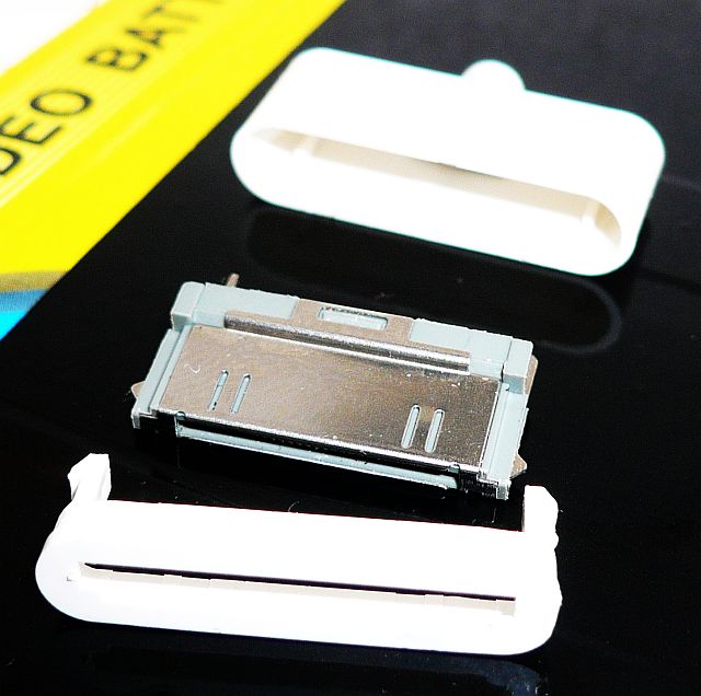
The cable is set up simply, in the picture you can see that the near white frame with snaps is inserted into the connector body, and fixes the contact group itself. Understands, respectively, with the help of vykolupyvaniya near the frame on the side of something sharp.
The cable must be unsoldered from the connector, and gut the second USB, in order to add pins to the first.
Here is the back side of the contact group:

There are no pins on this photo (this is a photo of the donor). The numbering of pins from right to left (in the picture), the involved conclusions sit in wide slots. This is just 1 (land), 15, 16 (also land), 23 (+ 5V), 25 (D-), 27 (D +), 30 (land). Pins are only in four of them (savings!), Namely 16, 23, 25, 27. Our task is to add pins from the second cable to positions 3, 4, 11, 15. To do this, use pin pliers to be pulled out of the donor, carefully inserted ( subject to position) in the desired position on the recipient. To the end, of course, he will not fit, because you need to bring it to its normal position with a soldering iron. It is necessary to control the installation of the pin on the back side of the connector; its serial number is also checked there.
Now we have to combine the stand body and the connector. I acted simply - I circled the contour of the connector body with a sharp “scratch”, screwed holes F 1mm around this contour, and cut it with a clerical knife. It turned out neatly, the connector was sitting tight. To fully consolidate the success left to put it on the glue, I did not invent anything new, and glued it with superglue. Keeps perfectly.
Now we unsolder the necessary wires on the connector, we withdraw them to the case. To isolate neighboring pins, I highly recommend using a shrinkage of 2-3mm.
We are looking for a place where to plug the Bluetooth card. This is what should (although I hope that it will be more accurate) to end up with:

Immediately by mounting, we solder a divider (R2-R5 resistors) circuits, Bluetooth charging diodes, and R1 resistor. Display the signal wires through the side of the case.
Hooray! Almost done. It remains to think of how and where to put this creation in the car.
I did not think for a long time (and I do not hesitate to spoil the interior of the car), and screwed this block on two hefty screws directly to the panel. Like this:

NDA, with screws I certainly overdid it. Anyway.
What else did I not mention?
The Bluetooth status LED in my design was on the back of the board. I led the light guide to the front side of the case (on light trees it can be broken, for example).
I placed the remote microphone unit with the call reception button right behind the wheel above the dashboard, it is convenient to press, and audibility is even nothing.
Speaking of the microphone, in the telephone headsets, the end button is connected in parallel with the microphone, and it must be cut off and connected with separate wires.
Circuit solutions that I applied are controversial. For example, charging a lithium battery through two diodes is rightly considered a heresy. But in this particular case, nothing terrible will happen, the battery charging voltage will not exceed 3.8V, which is quite safe. The charging current will depend heavily on the degree of battery discharge, but at the lower limit the current will not exceed 200 mA.
Results:
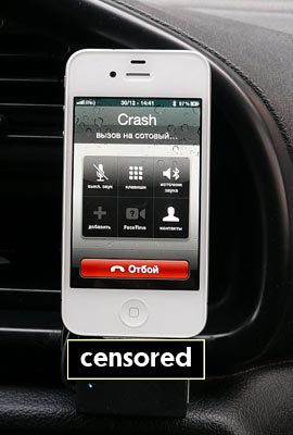
Stuck turned out comfortable. Navigator while driving is not only perfectly visible, but also audible. Music plays qualitatively, it is convenient to switch tracks. The sound of the conversation is a bit muffled and noisy compared to the old (fully wired) hands-free kit, but the audibility is still good. But the interlocutor began to hear me better - the case is most likely in the noise reduction algorithms of the Bluetooth headset. The noise from the engine disappeared completely.
A fly in the ointment too. The fact is that when the iPhone charges and plays music, a parasitic earth circuit is formed, through which the charging current flows. This current creates a voltage drop on the ground wire, and hence a tip in the speaker. Lead is not too strong, although audible. Positively, the noise disappears at 100% charge of the phone, the noise is also not audible when the iphone is silent.
Well, screws also violate harmony.
The cost of the solution is quite affordable. Even if you buy every component, including headsets, USB cables, SMD elements, heat shrink, superglue and screws, the cost of the entire set will not exceed 25-30 cu Budget!
Source: https://habr.com/ru/post/135676/
All Articles