Robot-turtle on ATMega8
They told me about their “robot crafts” and I also decided to share mine.
I was inspired by the robot Polulu 3pi . But I decided to make my own, although as it turned out later it was more difficult and, most importantly, much more expensive. But this stuff)
He stuffed various schemes in various forums: an engine control circuit , an infrared sensor control circuit , and the whole thing started at AtMega8.
Vobshchem something turned out like this animal

There are two TSOP and 3 IR LEDs ahead. Below 5 LEDs and 5 phototransistors. In general, something can follow the lines and can detect obstacles.
Inside, a little more about the robot, a couple of photos and videos
')
A lot of time I killed him. Many evenings. But now I know how to poison the circuit boards, what a nasty ferric chloride and how it doesn’t wash properly from clothes and what bad stains it leaves on the table. I learned how to tinker and solder, although I knew how to do it before, but only after the robot did I understand how correctly.
But all this stuff) The pleasure of the result brightens up everything.
The IC for TSOPs is engaged in the generation of pulses by the MK, and it also monitors the responses from them and the control of the engines.
Behind

and bottom

All parts, motors, sensors, etc. placed together on a circuit board.
He drew the scheme himself in Korela)

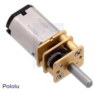
The motors are like that
But a small video - the truth on the video is a robot with a slight revision - there are more batteries.
At the moment I froze a little work on the robot. There is no time.
But in the near future it is to revive it and make some improvements.
1. put the batteries (I already bought them - from dekt-phones - the most it), and then the batteries quickly sit down.
2. On the shaft of each wheel, I will hang the wheel and the sensor from the old ball mouse. This way I can track the number of wheel revolutions and turn the wheel to the angle I need. This will allow you to manage the movement movement very flexibly. Yes ... for this, I will have to remove several phototransistors ... Rather, I will have to remove 4 and leave one in the middle. But in general, the task to move along the black line is no longer worth it. Therefore, one pair of CD + FT is enough to detect, for example, the edge of the table.
3. Make a complete separate power for MK and engines.
Collected from pieces by manual, so do not judge strictly :)
I myself understand that it is possible to do this easier ... But I am not a programmer, therefore, using the method of scientific typing)
I was inspired by the robot Polulu 3pi . But I decided to make my own, although as it turned out later it was more difficult and, most importantly, much more expensive. But this stuff)
He stuffed various schemes in various forums: an engine control circuit , an infrared sensor control circuit , and the whole thing started at AtMega8.
Vobshchem something turned out like this animal
There are two TSOP and 3 IR LEDs ahead. Below 5 LEDs and 5 phototransistors. In general, something can follow the lines and can detect obstacles.
Inside, a little more about the robot, a couple of photos and videos
')
A lot of time I killed him. Many evenings. But now I know how to poison the circuit boards, what a nasty ferric chloride and how it doesn’t wash properly from clothes and what bad stains it leaves on the table. I learned how to tinker and solder, although I knew how to do it before, but only after the robot did I understand how correctly.
But all this stuff) The pleasure of the result brightens up everything.
The IC for TSOPs is engaged in the generation of pulses by the MK, and it also monitors the responses from them and the control of the engines.
Behind
and bottom
All parts, motors, sensors, etc. placed together on a circuit board.
He drew the scheme himself in Korela)
The motors are like that
But a small video - the truth on the video is a robot with a slight revision - there are more batteries.
Shot, as it should, on the stapler ...
At the moment I froze a little work on the robot. There is no time.
But in the near future it is to revive it and make some improvements.
1. put the batteries (I already bought them - from dekt-phones - the most it), and then the batteries quickly sit down.
2. On the shaft of each wheel, I will hang the wheel and the sensor from the old ball mouse. This way I can track the number of wheel revolutions and turn the wheel to the angle I need. This will allow you to manage the movement movement very flexibly. Yes ... for this, I will have to remove several phototransistors ... Rather, I will have to remove 4 and leave one in the middle. But in general, the task to move along the black line is no longer worth it. Therefore, one pair of CD + FT is enough to detect, for example, the edge of the table.
3. Make a complete separate power for MK and engines.
Source firmware.
Collected from pieces by manual, so do not judge strictly :)
/************************************************ *************************************************/ #include <avr/io.h> #include <avr/delay.h> #define F 8000.0 // F, , #define N 20L // N, #define S 2L // S, #define t (unsigned long)((1/F)*1000000.0/2.0) // t, , #define Tp (unsigned long)(N*(t*2)) // Tp, , #define Td (unsigned long)(Tp*(S-1)) // Td, , void init(void) { DDRD = 0x00; DDRB = 0xff; DDRC = 0xff; PORTB = 0xff; PORTC = 0xff; PORTD = 0xff; PORTB |= _BV(PB1); PORTB |= _BV(PB2); } void rMotorF(void) { PORTC &= ~_BV(PC4); // "0" PORTC |= _BV(PC2); // "1" } void lMotorF(void) { PORTC &= ~_BV(PC5); // "0" PORTC |= _BV(PC3); // "1" } void rMotorB(void) { PORTC &= ~_BV(PC2); // "0" PORTC |= _BV(PC4); // "1" } void lMotorB(void) { PORTC &= ~_BV(PC3); // "0" PORTC |= _BV(PC5); // "1" } void IRGenerate(void) { int i; for (i = 0; i < N; ++i) // - { PORTC |= _BV(PC1); _delay_us (t); PORTC &= ~_BV(PC1); _delay_us (t); } } int main(void) // { init(); PORTC |= _BV(PC0); PORTB |= _BV(PB0); while (1) { IRGenerate(); if (!(PIND & (1 <<PIND7))) // { rMotorB(); // _delay_ms(50); } else { rMotorF(); // _delay_ms(50); } _delay_us(Td); IRGenerate(); if (!(PIND & (1 <<PIND6))) // { lMotorB(); // _delay_ms(50); } else { lMotorF(); // _delay_ms(50); } _delay_us(Td); // } } I myself understand that it is possible to do this easier ... But I am not a programmer, therefore, using the method of scientific typing)
Source: https://habr.com/ru/post/135570/
All Articles