We build a tracked Bluetooth robot with a camera. Part 2
Part 1
Part 3
We continue to build a tracked robot.
In the first part, we picked up and, I hope, ordered all the necessary parts. By the way, I recently checked that all Tamiya parts (tracks, platforms, gearbox) were in stock at Terraelectronica. More expensive, of course, than from China, but nearby.
Those who have already received the parts, probably already assembled the chassis.
Now we will deal with onboard electronics, video subsystem and power.
Motors are already connected to MotorShield. It's time to connect with the PC.
To do this, take the Bluetooth module and connect its pins T and R to pins 0 (Rx) and 1 (Tx) Arduino. + and - we connect respectively to pins +5 and GND. Do not confuse the polarity of the power supply - the module may burn out.
When powering on the Arduino module should flash LED - it is ready to connect.
We go to the PC, we are looking for a bluetooth device with the name “linvor” - this is the name of the module by default. In the future, it, as well as the speed of work can be changed using AT commands. (In particular, I configured mine to 115200 instead of 9600 and gave the name "BT1"). We pair the PC with the module using the code "1234". The system should have 2 COM ports - one for outgoing connections, the other for incoming. We are interested in exactly the first.
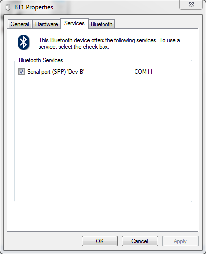
Write down the COM port number, it will come in handy later for us to connect. If there are two ports in the properties of the device and you cannot determine which is outgoing, write both down, determine later using the poke method.
At first I ordered this kit:

But when I tried to get rid of the thick lace, I burned the camera. If you are careful, then all you need is to fix the camera on the robot with a cog and apply 12V to it (from 9V, contrary to the statements of the Chinese, it does not work for me). The transmitting part is ready.
For the receiving part, there are two ways - buy a small TV for 4-7 "(I recently bought one myself) or connect it to a PC / laptop.
For the second option, we will need to connect EasyCAP to the PC, install the driver and install any program that can display an image from the video capture device. I am using DScaler .
And in order to make it easier to use, I embedded the receiver and EasyCAP in the box from the receiver kit with the camera. There you can also put the battery to power the receiver. To do this, I cut holes in the rear wall for the antenna connector, receiver trim knobs and for the EasyCAP USB connector.
Inside the box, connect the receiver's outputs to the CVRS and Audio inputs (if there is a microphone on the camera). After removing the handle and antenna, push the receiver and EasyCAP into the holes. We fix both devices to the bottom with double-sided or ordinary scotch tape.

" 1.2GHz Receiver + EasyCAP "
Outside, screw on the antenna and put on the cap and handle. Connecting EasyCAP to a PC or laptop will be a complete extension cord.

" 1.2GHz Receiver + EasyCAP "
At this stage, it is useful to turn on the power to the camera, turn on the receiver and try connecting to DScaler first to EasyCAP (the device can be seen as USB VideoGrabber) and then using the tuning knob on the receiver to catch the signal from the camera.
If everything is collected correctly, congratulations - the video link is ready, you can indulge in it.
If you ordered a pan-tilt (PanTilt) pad and servo drives, then you need to assemble a camera mount. All connections are made with the usual superglue, but be careful, servo drives stick tight! Therefore it is worth checking everything twice.
The camera on the platform is fastened with the connector down, towards the rotatable (Pan) servo.
Before installing the camera, find the middle position of the rotary servo and put on the rocking chair in this position so that the camera is looking forward, fasten it with a screw.
To the rotary servo I cut a bracket from white acrylic, with which it is a little more convenient to attach the entire structure to the platform. You can directly with a long cog M3 or with the help of the U-shaped parts of the designer, like mine:
The servo drive is attached to the bracket itself with complete screws. The designer screws are M4, so I had to drill holes in the board a little.
Servomotors are connected as follows: brown and red wire - +5 and Gnd, respectively, orange - control signal. The signal wire of the rotation servo is connected to the D10 pin of the Arduino, the signal wire of the camera tilt servo is connected to the D9 pin. On the sensor shield there are convenient three-pin connectors GND, VCC, Dx for each digital pin Arduino. Made specifically for this occasion - the plug connects directly without additional wiring.
')
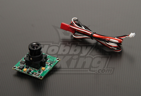
Since I burned my camera, and its quality was not particularly high, I bought a Sony 1/3 "CCD module
Fortunately, the transmitter of the murdered camera survived, and I soldered it directly to the Sony camera, carefully dropping it out of the burnt-down cheap camera.
I combined the power of the camera and the transmitter by soldering to one plug and tightening it into heat shrinkage.
The transmitter has a yellow wire - a video input, a white one - an audio input, red and black as usual - + power and ground, but the power is from the transducer built into the cord, so you need to remember which wire went to the transmitter when you unsolder. I did it like this:

" Sony CCD camera & 1.2GHz Transmitter "
The transmitter heats up during operation, but this is a feature of its design, something the Chinese have namuzhili with power, apparently.
Motors and Arduino will be powered from the same source, for this we set the Ext / Ard switch on MotorShield to the Ard position. Now the voltage of 7-12V can be fed through a standard Arduino power connector or via a MotorShield terminal block.
To power the camera and the transmitter, you can use either a separate 12V batteryor such a booster (recently sold):
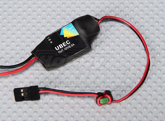
Unfortunately, in the description on the HK error - from 2S it does not work, you still need 12v (3S) and more at the input.
The battery is installed on the first floor. Front floors can be fastened with a metal bracket from the designer so that the second floor does not hang out.
Hooray, the hardware is ready. It remains to write the firmware for the microcontroller and the program for the PC.
PS Question - on New Year's holidays, is anyone going to do this or postpone writing the last article to the middle of January?
Part 3
We continue to build a tracked robot.
In the first part, we picked up and, I hope, ordered all the necessary parts. By the way, I recently checked that all Tamiya parts (tracks, platforms, gearbox) were in stock at Terraelectronica. More expensive, of course, than from China, but nearby.
Those who have already received the parts, probably already assembled the chassis.
Now we will deal with onboard electronics, video subsystem and power.
Bluetooth
Motors are already connected to MotorShield. It's time to connect with the PC.
To do this, take the Bluetooth module and connect its pins T and R to pins 0 (Rx) and 1 (Tx) Arduino. + and - we connect respectively to pins +5 and GND. Do not confuse the polarity of the power supply - the module may burn out.
When powering on the Arduino module should flash LED - it is ready to connect.
We go to the PC, we are looking for a bluetooth device with the name “linvor” - this is the name of the module by default. In the future, it, as well as the speed of work can be changed using AT commands. (In particular, I configured mine to 115200 instead of 9600 and gave the name "BT1"). We pair the PC with the module using the code "1234". The system should have 2 COM ports - one for outgoing connections, the other for incoming. We are interested in exactly the first.
Write down the COM port number, it will come in handy later for us to connect. If there are two ports in the properties of the device and you cannot determine which is outgoing, write both down, determine later using the poke method.
Video subsystem
At first I ordered this kit:
But when I tried to get rid of the thick lace, I burned the camera. If you are careful, then all you need is to fix the camera on the robot with a cog and apply 12V to it (from 9V, contrary to the statements of the Chinese, it does not work for me). The transmitting part is ready.
For the receiving part, there are two ways - buy a small TV for 4-7 "(I recently bought one myself) or connect it to a PC / laptop.
For the second option, we will need to connect EasyCAP to the PC, install the driver and install any program that can display an image from the video capture device. I am using DScaler .
And in order to make it easier to use, I embedded the receiver and EasyCAP in the box from the receiver kit with the camera. There you can also put the battery to power the receiver. To do this, I cut holes in the rear wall for the antenna connector, receiver trim knobs and for the EasyCAP USB connector.
Inside the box, connect the receiver's outputs to the CVRS and Audio inputs (if there is a microphone on the camera). After removing the handle and antenna, push the receiver and EasyCAP into the holes. We fix both devices to the bottom with double-sided or ordinary scotch tape.
" 1.2GHz Receiver + EasyCAP "
Outside, screw on the antenna and put on the cap and handle. Connecting EasyCAP to a PC or laptop will be a complete extension cord.
" 1.2GHz Receiver + EasyCAP "
At this stage, it is useful to turn on the power to the camera, turn on the receiver and try connecting to DScaler first to EasyCAP (the device can be seen as USB VideoGrabber) and then using the tuning knob on the receiver to catch the signal from the camera.
If everything is collected correctly, congratulations - the video link is ready, you can indulge in it.
Pan & Tilt
If you ordered a pan-tilt (PanTilt) pad and servo drives, then you need to assemble a camera mount. All connections are made with the usual superglue, but be careful, servo drives stick tight! Therefore it is worth checking everything twice.
The camera on the platform is fastened with the connector down, towards the rotatable (Pan) servo.
Before installing the camera, find the middle position of the rotary servo and put on the rocking chair in this position so that the camera is looking forward, fasten it with a screw.
To the rotary servo I cut a bracket from white acrylic, with which it is a little more convenient to attach the entire structure to the platform. You can directly with a long cog M3 or with the help of the U-shaped parts of the designer, like mine:
The servo drive is attached to the bracket itself with complete screws. The designer screws are M4, so I had to drill holes in the board a little.
Servomotors are connected as follows: brown and red wire - +5 and Gnd, respectively, orange - control signal. The signal wire of the rotation servo is connected to the D10 pin of the Arduino, the signal wire of the camera tilt servo is connected to the D9 pin. On the sensor shield there are convenient three-pin connectors GND, VCC, Dx for each digital pin Arduino. Made specifically for this occasion - the plug connects directly without additional wiring.
')
Since I burned my camera, and its quality was not particularly high, I bought a Sony 1/3 "CCD module
Fortunately, the transmitter of the murdered camera survived, and I soldered it directly to the Sony camera, carefully dropping it out of the burnt-down cheap camera.
I combined the power of the camera and the transmitter by soldering to one plug and tightening it into heat shrinkage.
The transmitter has a yellow wire - a video input, a white one - an audio input, red and black as usual - + power and ground, but the power is from the transducer built into the cord, so you need to remember which wire went to the transmitter when you unsolder. I did it like this:
" Sony CCD camera & 1.2GHz Transmitter "
The transmitter heats up during operation, but this is a feature of its design, something the Chinese have namuzhili with power, apparently.
Nutrition
Motors and Arduino will be powered from the same source, for this we set the Ext / Ard switch on MotorShield to the Ard position. Now the voltage of 7-12V can be fed through a standard Arduino power connector or via a MotorShield terminal block.
To power the camera and the transmitter, you can use either a separate 12V battery
Unfortunately, in the description on the HK error - from 2S it does not work, you still need 12v (3S) and more at the input.
The battery is installed on the first floor. Front floors can be fastened with a metal bracket from the designer so that the second floor does not hang out.
Hooray, the hardware is ready. It remains to write the firmware for the microcontroller and the program for the PC.
PS Question - on New Year's holidays, is anyone going to do this or postpone writing the last article to the middle of January?
Source: https://habr.com/ru/post/135371/
All Articles