Android + Arduino + 4 wheels
I did not think that it would twist me like that, but a rather acute attack of robotics happened. Well, like any self-respecting victim, I will try to infect as many people as possible.
How the insanity developed, I decided to describe in the article. It turned out long, but maybe someone will be interested. I think the article is aimed at those who have not yet practiced in robotics.
That's what happened as a result. The video is vintage, filmed by the owner of the iPhone, and they are entertainers, you know. The sound I left behind the scenes deliberately, so that everything buzzed as if in truth.
')
The next couple of paragraphs are purely lyrical, and can be missed by a stern technical reader.
It all started with lunch in the office. There were several of us, and one employee asked if anyone had a hobby. We thought, thought and suddenly realized that no one had a hobby. There is, of course, a craving for programming, there are sports activities, families and friends, but so that the houses from matches glue, cut the boats or make stamps - no, this did not happen. I do not know from greed or any other feelings, but the thought of the absence of a beloved affair stuck in my head. The rise, the road to work, work, the road home, a maximum of an hour with the family (everyone has it all!), Sleep ... At night, apparently, there is some sort of reset, and the next morning a new iteration begins. That employee as if thrust the wiring with feedback to my head. And not only me. The victims of that dinner, as it turned out soon, were two. The subject of interest to both of us was robotics. As a child I was a radio amateur, I graduated from the institute with a degree in robots, robotic systems and complexes, and now I am a software developer. This hobby is just made for me. Where have I been before?
In the office, we called for robots and a robobit, but there were no more volunteers. There were sympathizers, but there were only two participants left. We decided that everyone would make their own robot and on the appointed date (the deadline was about two months), we will clash in battle. The sense of beauty and the rejection of violence forced us to abandon sledgehammers, Bulgarians and other tools of savages in favor of the infrared gun and infrared receiver. Although, over time, the idea of the RoboBattle ceased to touch me, because now I had a robot (my beauty, naturally) and a lot of plans for its development, I must admit, the fact that the RoboBattle was held, really spurred me on the terms. It was a great motivator, he forced to seek out the time and hurry.
Well, now to the point. I would like to describe how the manufacture of my robot progressed, what problems I encountered, how I solved them and the most frequent question for me: how much money it all cost me.
Initially, I assumed that for the control system (in the future of the brain) of the robot I would use the Arduino platform. My "adversary" was moving along the same path. The topic was new for us, so, rummaging through the Internet, we found that everything is in the Arduino world: Ethernet Shield, Bluetooth Shield, Motor Shield, gyroscopes, accelerometers and a whole bunch of other sensors and interface boards that might be useful to geeks like us. But the more I looked for useful nodes for my robot, the more I became convinced that I already had it. In the smartphone. I have HTC Sensation with Android 2.3.4 on board. And there already is: Bluetooth, WiFi (even WiFi router), camera, flashlight, huge display, sound, microphone, microUSB, memory, gyroscope, compass. And here I decided that the brain of my robot will move to the smartphone. And Arduino will perform the functions of the spinal cord. Let him take commands, execute them and collect data from the sensors, then to transfer them to the brain.
This architectural solution has a big minus - it seems that at the end of the article I will have to include the cost of my smartphone in the cost of the robot, but I already had a smartphone, but I could not go past the advantages that he presented to me. Besides, for work, I was interested in the topic of programming under the Android OS, and such a decision was most welcome. My robot is not yet ready for autonomous actions, this is a topic for further development of the project, so another layer in the robot control was born - a simple client program that generates control commands and sends them via a TCP socket to an Android application. Such a program can be written for any platform, if only you can establish a connection via a TCP socket. Now I have written a simple .NET application using XNA. To control the robot, I use the XBOX 360 gamepad.
Approximately I will outline who is busy.
Arduino-sketch features:
Android application features:
.NET application features:
I didn’t have a big problem with software implementation of functions, except that Java programming was new for me (Android application level), but these are my personal difficulties. Sketches on Arduino did not cause any difficulties - a very simple language (Wiring), quite a tolerable development environment. What I had to do was to control the robot. I wrote the application in C #, and it is still very simple and simple, but the robot control algorithms had to be refined twice - I was not immediately able to achieve good controllability by the robot. But I am running ahead, I will write about it below.
I considered the timeline rather tight or it’s me so slow, so I made the following plan for myself:
I needed the first item of the plan for “warming up”. It was necessary to understand what Arduino is, set up a development environment, get used to a new language, write a couple of test sketches. For experiments, I purchased a ready-made set of "Matryoshka X" . Please do not take the link as a commercial advertisement, but Amperka turned out to be a very convenient resource. There are a lot of educational information, video tutorials, a forum. Having played enough with LEDs, it is time to move on.
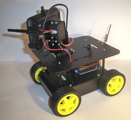
What I wanted from the mobile platform of the robot: that it was small enough for convenient maneuvering in the apartment, that it was fast, and that the carpets, sills and wires from extension cords it met were not an impassable obstacle for it. Well, and, of course, there should be enough space for the Arduino electronics and the smartphone. Underneath all this, such a four-wheeled platform came up perfectly.
The platform consists of electrics, except for four engines with gearboxes, a toggle switch and an external power connector. The connector is compatible with the Arduino Uno power connector and was very useful later when testing.
Here is my first photo of the cart:
There are five AA batteries in the holder that comes in the kit. As it turned out later, I lacked batteries for four engines, two servo drives and electronics. And then the beauty of my cart opened up. I got hold of 12 volt Ni-MH battery packs. So it turned out that instead of the standard holder for 5 AA, two battery assemblies with ten cans of AA each can fit in the cart. These are 20 AA cans! I switched on the assemblies in parallel, receiving 12 V and 2200 mAh. True, now I had to spend money on the charger for this mini-monster. And again the external power connector came in handy. I now also use it to charge the robot battery.
An additional nice bonus platform - a regular place for mounting the servo.
The only disadvantage of the trolley I encountered is the loose installation of the wheels on the shafts of the gearboxes. When assembling the wheel mount seemed reliable, but with the very first tests of the robot on the carpet, the wheels began to fall off. The design of the wheel did not involve screwing it in - just a snug fit, I did not want to glue the wheels, so I had to drill them and fix them on the gearbox shaft with ordinary screws. Fortunately, there are holes in the shafts of the gearboxes.
So, in the next step, I wanted to get from the platform movement. For this, I purchased “Motor Shield v3” from “Freeduino.ru”. It allows you to control four DC motors or two stepper motors, as well as connectors for two servo drives installed on it. In addition, the motor shield supports SPI. It seemed to me then a wonderful option, even redundant - I needed to control two servo drives and only two DC motors (for the left and right side, the front and rear motors are connected in parallel). Moreover, I managed to control the motors and servo drives, and I even closed this point of my plan.
Problems with “Motor Shield v3” started later. When I purchased USB Host Shield from DFRobot for pairing with a smartphone, I started having conflicts over the Arduno digital outputs used. I tried the usual control mode of this motor shield, and SPI - the best I achieved was the control of motors and servo drives, but I didn’t have more free exits. But still it was necessary to control the infrared gun. As I understand it, the problem was purely software. The libraries that I used are taken there, on freeduino.ru. They are dated December 2009. The site states that the modification of the library to work with SPI has not been tested on stepper motors, but in the near future, they promise to do it. And God be with them, with these stepping motors, only the date of the library is 2009. Looks like the project is abandoned. I honestly looked at the source code, sighed, and realized that I really did not want to delve into it. Another time somewhere in the future somehow another time sometime later. Of course, I could do with only one servo, but I really didn’t want to limit myself.
In theory, to control two engines, I need four legs of the controller, two more I need for servo drives, one for firing from the IR gun and four for controlling USB Host Shield. Total eleven legs. I did not use the zero and first legs - this is the TX and RX of the Arduino Uno serial port. Generally speaking, they can be used, but this enterprise is risky, as far as I understand it - you have to be ready for reprogramming the controller. Therefore, I left those legs alone. So, I went through all the thirteen legs of the Arduino Uno. I just didn’t succeed in forcing “Motor Shield v3” to use two legs for a motor or four legs for a SPI bus.
I had to buy another motor shield. Manufacturer DFRobot. The name is not particularly original: “2A Motor Shield For Arduino” . But it is simple and for control it needs only four digital outputs of the Arduino (two of them must be with PWM). Even the finished library is not needed. True, there are no connectors for servos, but these are trifles.
At this step, I formulated the robot's command system and, one might say, received an almost final version of the Arduino-sketch. When connected via USB, the Arduino connects as a normal serial port. Commands can be transferred to it by any terminal client. At first, I used Serial Monitor, part of the Arduino IDE. I quickly got tired of hammering teams, and for tests I wrote a WinForm application with three sliders (for controlling motors and a horizontal servo drive), which allowed me to test my sketches and conduct the first experiments with robot controllability.
The command system is simple: all commands are five-character, with the first two characters representing the command itself, and the remaining three characters - digital, determine the value of the parameter. For example:
LF190 - left engine forward (left forward) with a speed of 190 (speed is set from 000 to 255);
HH045 - set the horizontal angle of rotation of the head (head horizontal) to 45 degrees.
Then I had to learn and suffer. At first, I thought that connecting Arduino to Android would be as easy as connecting to Windows. In the Android application, I will receive a serial port and will write commands for Arduino into it. So easily it did not work. It turns out that the COM port in the Android device is hidden somewhere far away. I admit that I did not understand something - I did not have time for research. Studying the question, I found the project “android-serialport-api” . There is even a section dedicated to the activation of the serial port on HTC phones. And three models are considered: Dream, Magic and Hero. My not here. What else stopped me is that to activate the first thing to do is “Root your phone”. I haven’t ruled my phone and I’m not really going to do it yet.
Therefore, I went on another found by me, and already pretty trodden by all the way: Android Open Accessory Development Kit . In DevGuide, everything is described in sufficient detail, the only thing I didn’t like was some kind of crazy DemoKit example shown there. The example includes everything that is possible at once: the connection, the connection definition, the data transfer, the reception, the control of several LEDs, the motors, the work with the joystick, and the rather sophisticated (at least for me) activity in the Android application. Not having mastered the source code of the example from the first installment, I found its simplified version and everything immediately fell into place.
Having bought and installed USB Host Shield from DFRobot, I managed to transfer commands from my Android application to the Arduino-sketch, but then I got covered with two problems at once. One described above is some kind of conflict with my first motor shield (I'm sure the problem is in the motor shield control library from freeduino.ru). But the second I could not yet decide. It will be great if someone tells you what to do. USB Host Shield is the host in the USB connection (sorry for this inference). This means that the power comes from the USB Host Shield to the smartphone. And my overgrown smartphone begins to eat and so often suffering from malnutrition from a Krone-type battery or five AA batteries a trolley. So the idea was born to put the batteries. 12V and 2200 mAh is a great help in the supply of engines, servo drives and smartphones, but I really want to exclude the smartphone from this food chain. Nothing was found in the phone options. It seems that there will be no software solution without rutting the phone again. Then I had only a hardware solution to the problem. The USB cable contains four lines: power, ground, transmission line, and receiver line. The first idea - to cut the food - failed. After that, the smartphone stops detecting connections with a USB host. Again, digging on the Internet, I found the person who solved this problem. Simon Monk achieved disabling the charging of his Nexus One when connected to Host Shield USB in a similar bundle with the Arduino. To do this, he installed a 1 kΩ resistor across the power line of the USB cable. He received this resistance empirically, when the connection definition (accessory detection) was already triggered, and the charge of the phone had not yet begun.
I put a kilohm resistor across the line and tried to connect a smartphone. The connection was found, and immediately started charging the smartphone battery. Then I put a variable resistor at 10 kΩ. The effect is the same. Now added successively another 10 kΩ - accessory detection did not happen. And charging did not start. There was a moment of triumph, I began to slowly lower the resistance with a variable resistor, and on 16 kilo-ohms the smartphone discovered the Arduino. At the same time began charging the smartphone. Collapse. I also contrived a bit, unsubscribed to Simon in a comment to his post, so there is the last comment and hangs from Dmitry and has so far given up. In the end, with a 2,200 mAh, we have some wintertime.
What Simon draws attention to, and I fully join him, is that we all do experiments with a cable and our own phone at our own peril and risk. I had to say it.
So, I got the following configuration: a smartphone with my test application is connected to three floors of boards - USB Host Shield, Motor Shield and Arduino Uno. My test application on the smartphone sends commands to the cart to rotate the engines in different modes (change of speed, direction) and turn the servo at different angles. And then suddenly collapse again. Sometimes the commands are executed, and sometimes the cart behaves like a madman - it turns the wheels in different directions, then it rolls around with a servo drive, and these seizures have nothing in common with the transmitted commands.
It was strange that I had never encountered this problem before. Studying it, I understood: in a new configuration, power is produced from a single source - both the engines are powered, and the electronics are powered. And earlier, I always powered the Arduino with a separate source: either a Crohn battery or a USB cable from a PC. An experiment with an additional power source confirmed my theory. Apparently, on Arduino power supply, there are pickups from running engines. I looked at what they wrote about it. People with such a problem are encountered, as I understand it, in the world of quadcopter drivers, it is, this is the world of powerful electric motors, and perhaps I was dragged into it due to the inclusion of my engines in two parallel pairs. The current doubled, the noise increased, and my cart was drawn to the quadcopters.
I opened the topic on the forum in Amperk, but people with similar problems did not encounter it. I really didn’t want to use two power sources - this is somehow strange. I realized that it was enough for me to put a filter on the Arduino power input, but my technical abilities didn’t have enough for it, and the time for further searching was long over. The only thing that I managed to find from solutions to such problems is here . I decided to take a chance and bought a DC-DC converter TEN 8-1221. Input 12V converter turns into + 5V and -5V with a common contact of 0.8A each. I did a common -5V and got + 5V and + 10V. 10B went to power the Arduino and through its stabilizer to the USB Host and Motor Shield chips. I used 5V to power the servos to relieve the Arduino stabilizer a little. Also, as before, all the same 12V I applied to the motor shield terminals for external powering of the engines. But now I was hoping for a filter built into the DC-DC converter. I was lucky and my hopes were justified. Now the cart diligently executed all the commands of the Android test application.
Here, in my happiness, everything went smoothly. The idea was this: for interaction between a PC and a smartphone, either an external WiFi router is needed, or the HTC Sensation itself can act as a router. This is convenient, then you can control the robot even in the forest. I deliberately chose WiFi, not Bluetooth or, for example, XBee because of my far-reaching plans. For communication, the Android application opens a server socket, then the .NET application establishes a connection and sends commands to the robot. Everything was simple.
A useful option of my phone turned out to be that it can be switched to the “airplane” mode, all communications will be disabled, and then turn on the WiFi router. I don’t know if it’s a developer’s bug or a useful utility, but I like it. I can turn off GSM, 3G, Bluetooth and still use WiFi. I didn’t even do an Android service, but I managed to get an Android application.
Here, too, everything worked out without a hitch. The role of the gun is performed by the infrared LED TSAL4400, and for fixing the hit I used the photo detector TSOP31236. The IR LED operates on 100mA, and peak 200mA. The maximum allowed current at the Arduino digital output is 40 mA. Therefore, I recommend to put a transistor to control the IR-LED. Binding photoreceiver specified in its datasheet .
I send the IR signal (shot) and process the IR signal reception (hit), of course, in the Arduino-sketch. For this I use the IRremote library.
To narrow the infrared beam, I put the LED in a metal tube (I used part of the broken telescopic antenna section).
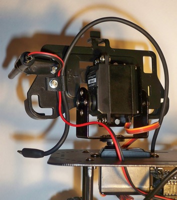
By this time, all the main and hardware and software problems were solved, but I managed to find myself another rake. It so happened that before that I had only one servo (DF05BB with a rotation angle of 180 degrees). The head of my robot should turn in a horizontal and vertical plane, so I attended to buying a second servo. I did not find exactly the same, but I found a more powerful one with a rotation angle of 360 degrees. I thought a great option for a horizontal plane. When bought, it turned out that I did not pay attention to two words in the description: "continius rotaiting". This means that servos do not rotate 360 degrees, but simply rotate. You can control the speed and direction of their rotation, but the angle of rotation can not be controlled. Previously, I did not know about the existence of such servos. I had to look for another one, since by the time my first servo drive had appeared in Amperk.
The next step is to install a vertical servo and mounting for the phone. As I already wrote, for mounting the horizontal drive on the trolley there is already a regular installation space, and for the vertical I purchased a special bracket .
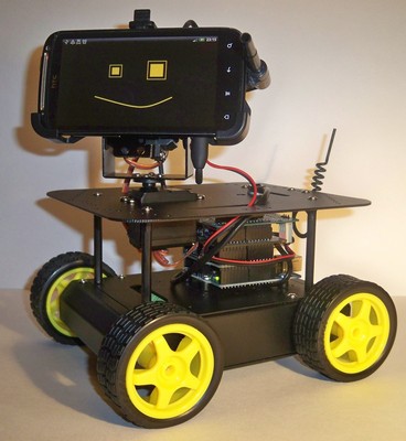
For installing my phone, the holder for HTC Sensation was ideally suited: HTC Z710e (Z710ECAR01) . I bought it specifically for the robot. The caps of the screws for attachment to the vertical servo bracket turned out to be recessed and do not harm the back wall of the phone.
There was little free space under the phone holder, and not every microUSB connector fit there. The connector of the proprietary USB cable from HTC is placed, and the cable itself is rather soft. I had to shorten it. At the other end, I put the USB-A (male) connector to connect to the USB Host Shield.
Now about the IR gun and IR receiver. The mount for the barrel of the gun is made of improvised means: for this role, the part from the half-toy clamp fit perfectly. I secured it to the left of the phone holder so that the gun did not interfere with the tilts of the robot’s head and the use of the “hardware” buttons of the smartphone if they were suddenly needed (the buttons are on the right). As I already wrote, the barrel is made of a telescopic antenna, and its sections are fixed with a shrink tube. I didn’t think too wisely with the IR receiver - in this form I only need it to conduct the Battle of the Battle, and then it can be removed (actually, a gun too). Therefore, I simply attached the receiver with double-sided tape on the back of the robot.
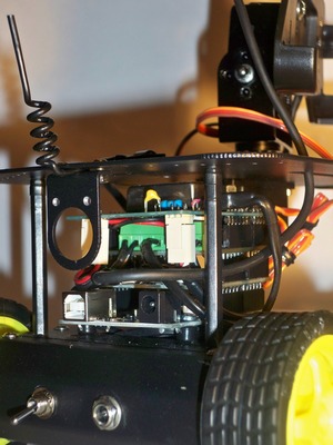
Well, a couple of words about electronics. To install a DC-DC converter, I bought a Proto Shield prototype card, and at the same time I soldered an IR receiver harness to cut off false positives. I also installed connectors for servo drives and a power connector for all my electronics. The 10-volt DC-DC converter output is directly connected to the Vcc and Gnd pins. Those. I do not use the Arduino Uno power connector. 5 volt DC-DC converter output is connected to the servo connectors. So it turned out four "floors" of boards. The fourth floor did not want to fit in the cart, I had to put small spacers to lift the top panel of the platform.
To release a robot, a face and, of course, a tail were required. I’m still a computer artist, so I only have Paint at hand. Somehow I painted four faces: happy, displeased, angry and killed to death. Then he corrected the management program to change moods. By the way, having tried both, I can say with confidence that programming is much easier. The tail is twisted from copper wire, stuffed into a heat shrink tubing and clamped between the back and the USB connector. Added sounds of gunshots and hits. It would be necessary still sounds under each mood.
In principle, with this one could already go out. But one more thing haunted me - the robot's handling.The implementation seems to be workable, but something was wrong. By tradition, the left joystick of the gamepad controls the movement. The right one is a review, i.e. head rotation. Deficiencies in the management were both there and there.
First, for those who do not know, a couple of words about joysticks. Gamepad joysticks at least under XNA give x and y coordinates in the range from -1 to +1. Point (0, 0) corresponds to the center position of the joystick. Moreover, the extreme positions of the joystick correspond to a circle with a radius equal to 1.
. , . . , . , , . x y 0 +1. (0, 0) (x, y). , , , x, . x . , , 0 ( ), , 90 , .
«» . , , X – , .
But one thing was not enough for ease of management. The values of the speeds throughout the above-described trigonometry varied from 0 to 1. I proportional to these values were transferred to values from 0 to 255 for setting the PWM on the motors. At small values, the engines only buzzed with different pitch, and then quite sharply picked up speed to the maximum. And intuitively it was perceived as discomfort when driving a cart. The output was in the addition of a non-linear relationship. For small values of the coordinate, for example, x, f (x) should grow rapidly. As x approaches 1, the growth of f (x) should slow down. The same for the y coordinate. The function of a circle with a center at the point (1, 0) and a radius of 1: f (x) = sqrt (2x - x ^ 2) suited me perfectly. After adding this transformation in both coordinates, the control became less sharp and more predictable.
And now about the right joystick and head rotation. My fault was that I converted the coordinates of the joystick into angles of rotation of the head proportionally. Those.the center position of the joystick corresponded to 90 degrees horizontally and 90 degrees vertically. This is the direction of gaze forward. I lie with the vertical because I introduced a software restriction on the angle of rotation vertically, and this was not 90 degrees, but the middle of the amplitude of the vertical deviation. But now it does not matter, we will consider 90 degrees, because my servos are rotated from 0 to 180 degrees. And what happened: at the coordinate of the joystick (1, 0), the head was turned to the right (0 degrees). At the coordinate (0, 1), the head is turned up (0 degrees). But if the joystick does not deviate horizontally or vertically, but diagonally, the head will no longer be able to get to zero degrees either through one or the other servo drive. The area of the joystick is a circle, so for example, the coordinate (1, 1) will not be available. Hence the conclusion:The circular area of the joystick with the center at the origin and a diameter of 2 must be “stretched” into a square area with the same center and side equal to 2. I solved this problem for the first half of the first quadrant (from 0 to 45 degrees), the other solutions were reflections. In short, the following happened:
x '= sqrt (x ^ 2 + y ^ 2)
y' = y * x '/ x
where (x', y ') are the new coordinates, stretched for a square, but only for the first half of the first quadrant.
Well, that's probably all. Having corrected controllability, I went to boast in the office.
I would like to warn you if you want to enjoy the process of creating a robot, show imagination, boast to your friends before it is too late, I advise you to go to the heading “Plans and conclusion”. This section worries me.
First, at the cost of parts directly robot:
That's the amount. Moscow prices. True, the details can be ordered in Chinese online stores. There prices differ amazingly: it turns out to be two or even three times cheaper. But you have to wait a long time. I had little time, although, I must admit, I would not have suffered.
Now, what else did I buy or have already had and without what the robot will not go:
After two months of midnight work, when I went through everything described above, my wife asked me: “No, I understand everything, but that you just can’t buy a radio-controlled machine?”
Skip the paragraph.
Yes. So far, what I have early to call a robot. I understand it. , . , , . .
, . , , «» «» , , , , . . , .
, , - .
UPD: code.google.com. , : robot-mitya .
I opened to view the entire source code. Here are all three levels of robot programming: a sketch for Arduino, an Android application and a Windows application. Subversion is used as a version control system. The tag folder contains a fully working release version 1.0.0. I checked its operation from scratch by downloading project source codes from the server, compiling them and executing them on the robot. In the Trunk folder, as always, the current branch of the project.
Arduino-sketch is written on IDE version arduino-0022. The IDE version with the libraries I use is uploaded to the downloads section .
When writing an Android application, the Eclipse IDE for Java Developers version of Indigo Service Release 1 with the Checkstyle code analysis plugin installed was used. The only concession that I allowed myself in the Checkstyle settings is an increase in the maximum string length from 80 to 160 characters. The remaining settings are left unchanged.
Microsoft Visual C # 2010 Express was used to develop a Windows application. For the analysis of the quality of the code used StyleCop. Express Studio version does not support embedding extensions, but the use of StyleCop is possible due to the possibility of its integration with MSBuild. The topic is wonderfully described in the article StyleCop & C # Express .
Good luck!
How the insanity developed, I decided to describe in the article. It turned out long, but maybe someone will be interested. I think the article is aimed at those who have not yet practiced in robotics.
That's what happened as a result. The video is vintage, filmed by the owner of the iPhone, and they are entertainers, you know. The sound I left behind the scenes deliberately, so that everything buzzed as if in truth.
')
Lyrics
The next couple of paragraphs are purely lyrical, and can be missed by a stern technical reader.
It all started with lunch in the office. There were several of us, and one employee asked if anyone had a hobby. We thought, thought and suddenly realized that no one had a hobby. There is, of course, a craving for programming, there are sports activities, families and friends, but so that the houses from matches glue, cut the boats or make stamps - no, this did not happen. I do not know from greed or any other feelings, but the thought of the absence of a beloved affair stuck in my head. The rise, the road to work, work, the road home, a maximum of an hour with the family (everyone has it all!), Sleep ... At night, apparently, there is some sort of reset, and the next morning a new iteration begins. That employee as if thrust the wiring with feedback to my head. And not only me. The victims of that dinner, as it turned out soon, were two. The subject of interest to both of us was robotics. As a child I was a radio amateur, I graduated from the institute with a degree in robots, robotic systems and complexes, and now I am a software developer. This hobby is just made for me. Where have I been before?
In the office, we called for robots and a robobit, but there were no more volunteers. There were sympathizers, but there were only two participants left. We decided that everyone would make their own robot and on the appointed date (the deadline was about two months), we will clash in battle. The sense of beauty and the rejection of violence forced us to abandon sledgehammers, Bulgarians and other tools of savages in favor of the infrared gun and infrared receiver. Although, over time, the idea of the RoboBattle ceased to touch me, because now I had a robot (my beauty, naturally) and a lot of plans for its development, I must admit, the fact that the RoboBattle was held, really spurred me on the terms. It was a great motivator, he forced to seek out the time and hurry.
Architecture
Well, now to the point. I would like to describe how the manufacture of my robot progressed, what problems I encountered, how I solved them and the most frequent question for me: how much money it all cost me.
Initially, I assumed that for the control system (in the future of the brain) of the robot I would use the Arduino platform. My "adversary" was moving along the same path. The topic was new for us, so, rummaging through the Internet, we found that everything is in the Arduino world: Ethernet Shield, Bluetooth Shield, Motor Shield, gyroscopes, accelerometers and a whole bunch of other sensors and interface boards that might be useful to geeks like us. But the more I looked for useful nodes for my robot, the more I became convinced that I already had it. In the smartphone. I have HTC Sensation with Android 2.3.4 on board. And there already is: Bluetooth, WiFi (even WiFi router), camera, flashlight, huge display, sound, microphone, microUSB, memory, gyroscope, compass. And here I decided that the brain of my robot will move to the smartphone. And Arduino will perform the functions of the spinal cord. Let him take commands, execute them and collect data from the sensors, then to transfer them to the brain.
This architectural solution has a big minus - it seems that at the end of the article I will have to include the cost of my smartphone in the cost of the robot, but I already had a smartphone, but I could not go past the advantages that he presented to me. Besides, for work, I was interested in the topic of programming under the Android OS, and such a decision was most welcome. My robot is not yet ready for autonomous actions, this is a topic for further development of the project, so another layer in the robot control was born - a simple client program that generates control commands and sends them via a TCP socket to an Android application. Such a program can be written for any platform, if only you can establish a connection via a TCP socket. Now I have written a simple .NET application using XNA. To control the robot, I use the XBOX 360 gamepad.
Functions
Approximately I will outline who is busy.
Arduino-sketch features:
- Establishing a connection with an Android application.
- Reception and execution of commands received from the Android application.
- Reception of signals from the sensors of the robot and the transfer of these signals to the Android application.
Android application features:
- Establishing a connection with an Arduino-sketch.
- Establishing a connection with a .NET application.
- Receive commands from a .NET application.
- Execution of the part of the received commands, not intended for the level of Arduino. For example, playing sounds, turning on the headlights (camera flash), changing the faces on the smartphone display, etc.
- Transmission of commands in Arduino.
- Receiving sensor signals from the Arduino.
- Response to sensor signals. For example, playing a sound when a “shot” from an IR gun is “hit” in my robot.
- Sending sensor signals to a .NET application.
.NET application features:
- Establishing a connection with an Android application.
- Input processing (XBOX 360 gamepad).
- Team building.
- Transfer commands to the Android application.
- Receive sensor signals from the Android application.
- Display the current status of the robot.
I didn’t have a big problem with software implementation of functions, except that Java programming was new for me (Android application level), but these are my personal difficulties. Sketches on Arduino did not cause any difficulties - a very simple language (Wiring), quite a tolerable development environment. What I had to do was to control the robot. I wrote the application in C #, and it is still very simple and simple, but the robot control algorithms had to be refined twice - I was not immediately able to achieve good controllability by the robot. But I am running ahead, I will write about it below.
My plan
I considered the timeline rather tight or it’s me so slow, so I made the following plan for myself:
- Mastering the Arduino controller.
- Assembling a cart, mounting electronics on it.
- Programming Arduino, offline command execution.
- Trolley control via USB PC.
- Connect the Arduino to an Android smartphone.
- Transmission of commands from the PC to the smartphone.
- Gun and hit sensors.
- Final assembly.
- Combing, documenting.
Mastering the Arduino controller
I needed the first item of the plan for “warming up”. It was necessary to understand what Arduino is, set up a development environment, get used to a new language, write a couple of test sketches. For experiments, I purchased a ready-made set of "Matryoshka X" . Please do not take the link as a commercial advertisement, but Amperka turned out to be a very convenient resource. There are a lot of educational information, video tutorials, a forum. Having played enough with LEDs, it is time to move on.
Assembly of the cart, installation of electronics on it
What I wanted from the mobile platform of the robot: that it was small enough for convenient maneuvering in the apartment, that it was fast, and that the carpets, sills and wires from extension cords it met were not an impassable obstacle for it. Well, and, of course, there should be enough space for the Arduino electronics and the smartphone. Underneath all this, such a four-wheeled platform came up perfectly.
The platform consists of electrics, except for four engines with gearboxes, a toggle switch and an external power connector. The connector is compatible with the Arduino Uno power connector and was very useful later when testing.
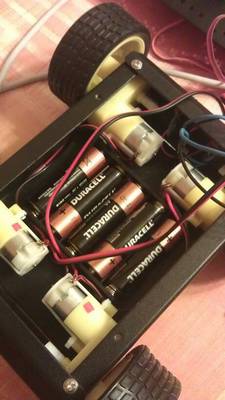
Here is my first photo of the cart:
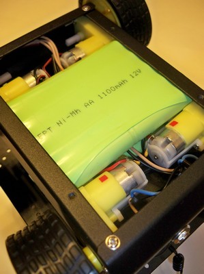
There are five AA batteries in the holder that comes in the kit. As it turned out later, I lacked batteries for four engines, two servo drives and electronics. And then the beauty of my cart opened up. I got hold of 12 volt Ni-MH battery packs. So it turned out that instead of the standard holder for 5 AA, two battery assemblies with ten cans of AA each can fit in the cart. These are 20 AA cans! I switched on the assemblies in parallel, receiving 12 V and 2200 mAh. True, now I had to spend money on the charger for this mini-monster. And again the external power connector came in handy. I now also use it to charge the robot battery.
An additional nice bonus platform - a regular place for mounting the servo.
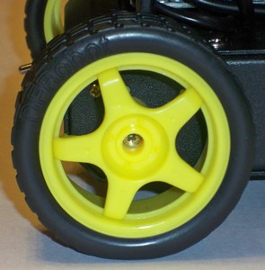
The only disadvantage of the trolley I encountered is the loose installation of the wheels on the shafts of the gearboxes. When assembling the wheel mount seemed reliable, but with the very first tests of the robot on the carpet, the wheels began to fall off. The design of the wheel did not involve screwing it in - just a snug fit, I did not want to glue the wheels, so I had to drill them and fix them on the gearbox shaft with ordinary screws. Fortunately, there are holes in the shafts of the gearboxes.
Programming Arduino, offline command execution
So, in the next step, I wanted to get from the platform movement. For this, I purchased “Motor Shield v3” from “Freeduino.ru”. It allows you to control four DC motors or two stepper motors, as well as connectors for two servo drives installed on it. In addition, the motor shield supports SPI. It seemed to me then a wonderful option, even redundant - I needed to control two servo drives and only two DC motors (for the left and right side, the front and rear motors are connected in parallel). Moreover, I managed to control the motors and servo drives, and I even closed this point of my plan.
Problems with “Motor Shield v3” started later. When I purchased USB Host Shield from DFRobot for pairing with a smartphone, I started having conflicts over the Arduno digital outputs used. I tried the usual control mode of this motor shield, and SPI - the best I achieved was the control of motors and servo drives, but I didn’t have more free exits. But still it was necessary to control the infrared gun. As I understand it, the problem was purely software. The libraries that I used are taken there, on freeduino.ru. They are dated December 2009. The site states that the modification of the library to work with SPI has not been tested on stepper motors, but in the near future, they promise to do it. And God be with them, with these stepping motors, only the date of the library is 2009. Looks like the project is abandoned. I honestly looked at the source code, sighed, and realized that I really did not want to delve into it. Another time somewhere in the future somehow another time sometime later. Of course, I could do with only one servo, but I really didn’t want to limit myself.
In theory, to control two engines, I need four legs of the controller, two more I need for servo drives, one for firing from the IR gun and four for controlling USB Host Shield. Total eleven legs. I did not use the zero and first legs - this is the TX and RX of the Arduino Uno serial port. Generally speaking, they can be used, but this enterprise is risky, as far as I understand it - you have to be ready for reprogramming the controller. Therefore, I left those legs alone. So, I went through all the thirteen legs of the Arduino Uno. I just didn’t succeed in forcing “Motor Shield v3” to use two legs for a motor or four legs for a SPI bus.
I had to buy another motor shield. Manufacturer DFRobot. The name is not particularly original: “2A Motor Shield For Arduino” . But it is simple and for control it needs only four digital outputs of the Arduino (two of them must be with PWM). Even the finished library is not needed. True, there are no connectors for servos, but these are trifles.
Trolley control via USB PC
At this step, I formulated the robot's command system and, one might say, received an almost final version of the Arduino-sketch. When connected via USB, the Arduino connects as a normal serial port. Commands can be transferred to it by any terminal client. At first, I used Serial Monitor, part of the Arduino IDE. I quickly got tired of hammering teams, and for tests I wrote a WinForm application with three sliders (for controlling motors and a horizontal servo drive), which allowed me to test my sketches and conduct the first experiments with robot controllability.
The command system is simple: all commands are five-character, with the first two characters representing the command itself, and the remaining three characters - digital, determine the value of the parameter. For example:
LF190 - left engine forward (left forward) with a speed of 190 (speed is set from 000 to 255);
HH045 - set the horizontal angle of rotation of the head (head horizontal) to 45 degrees.
Connecting the Arduino to an Android smartphone
Then I had to learn and suffer. At first, I thought that connecting Arduino to Android would be as easy as connecting to Windows. In the Android application, I will receive a serial port and will write commands for Arduino into it. So easily it did not work. It turns out that the COM port in the Android device is hidden somewhere far away. I admit that I did not understand something - I did not have time for research. Studying the question, I found the project “android-serialport-api” . There is even a section dedicated to the activation of the serial port on HTC phones. And three models are considered: Dream, Magic and Hero. My not here. What else stopped me is that to activate the first thing to do is “Root your phone”. I haven’t ruled my phone and I’m not really going to do it yet.
Therefore, I went on another found by me, and already pretty trodden by all the way: Android Open Accessory Development Kit . In DevGuide, everything is described in sufficient detail, the only thing I didn’t like was some kind of crazy DemoKit example shown there. The example includes everything that is possible at once: the connection, the connection definition, the data transfer, the reception, the control of several LEDs, the motors, the work with the joystick, and the rather sophisticated (at least for me) activity in the Android application. Not having mastered the source code of the example from the first installment, I found its simplified version and everything immediately fell into place.
Having bought and installed USB Host Shield from DFRobot, I managed to transfer commands from my Android application to the Arduino-sketch, but then I got covered with two problems at once. One described above is some kind of conflict with my first motor shield (I'm sure the problem is in the motor shield control library from freeduino.ru). But the second I could not yet decide. It will be great if someone tells you what to do. USB Host Shield is the host in the USB connection (sorry for this inference). This means that the power comes from the USB Host Shield to the smartphone. And my overgrown smartphone begins to eat and so often suffering from malnutrition from a Krone-type battery or five AA batteries a trolley. So the idea was born to put the batteries. 12V and 2200 mAh is a great help in the supply of engines, servo drives and smartphones, but I really want to exclude the smartphone from this food chain. Nothing was found in the phone options. It seems that there will be no software solution without rutting the phone again. Then I had only a hardware solution to the problem. The USB cable contains four lines: power, ground, transmission line, and receiver line. The first idea - to cut the food - failed. After that, the smartphone stops detecting connections with a USB host. Again, digging on the Internet, I found the person who solved this problem. Simon Monk achieved disabling the charging of his Nexus One when connected to Host Shield USB in a similar bundle with the Arduino. To do this, he installed a 1 kΩ resistor across the power line of the USB cable. He received this resistance empirically, when the connection definition (accessory detection) was already triggered, and the charge of the phone had not yet begun.
I put a kilohm resistor across the line and tried to connect a smartphone. The connection was found, and immediately started charging the smartphone battery. Then I put a variable resistor at 10 kΩ. The effect is the same. Now added successively another 10 kΩ - accessory detection did not happen. And charging did not start. There was a moment of triumph, I began to slowly lower the resistance with a variable resistor, and on 16 kilo-ohms the smartphone discovered the Arduino. At the same time began charging the smartphone. Collapse. I also contrived a bit, unsubscribed to Simon in a comment to his post, so there is the last comment and hangs from Dmitry and has so far given up. In the end, with a 2,200 mAh, we have some wintertime.
What Simon draws attention to, and I fully join him, is that we all do experiments with a cable and our own phone at our own peril and risk. I had to say it.
Unplanned surprise - Arduino power interference
So, I got the following configuration: a smartphone with my test application is connected to three floors of boards - USB Host Shield, Motor Shield and Arduino Uno. My test application on the smartphone sends commands to the cart to rotate the engines in different modes (change of speed, direction) and turn the servo at different angles. And then suddenly collapse again. Sometimes the commands are executed, and sometimes the cart behaves like a madman - it turns the wheels in different directions, then it rolls around with a servo drive, and these seizures have nothing in common with the transmitted commands.
It was strange that I had never encountered this problem before. Studying it, I understood: in a new configuration, power is produced from a single source - both the engines are powered, and the electronics are powered. And earlier, I always powered the Arduino with a separate source: either a Crohn battery or a USB cable from a PC. An experiment with an additional power source confirmed my theory. Apparently, on Arduino power supply, there are pickups from running engines. I looked at what they wrote about it. People with such a problem are encountered, as I understand it, in the world of quadcopter drivers, it is, this is the world of powerful electric motors, and perhaps I was dragged into it due to the inclusion of my engines in two parallel pairs. The current doubled, the noise increased, and my cart was drawn to the quadcopters.
I opened the topic on the forum in Amperk, but people with similar problems did not encounter it. I really didn’t want to use two power sources - this is somehow strange. I realized that it was enough for me to put a filter on the Arduino power input, but my technical abilities didn’t have enough for it, and the time for further searching was long over. The only thing that I managed to find from solutions to such problems is here . I decided to take a chance and bought a DC-DC converter TEN 8-1221. Input 12V converter turns into + 5V and -5V with a common contact of 0.8A each. I did a common -5V and got + 5V and + 10V. 10B went to power the Arduino and through its stabilizer to the USB Host and Motor Shield chips. I used 5V to power the servos to relieve the Arduino stabilizer a little. Also, as before, all the same 12V I applied to the motor shield terminals for external powering of the engines. But now I was hoping for a filter built into the DC-DC converter. I was lucky and my hopes were justified. Now the cart diligently executed all the commands of the Android test application.
Transmission of commands from the PC to the smartphone
Here, in my happiness, everything went smoothly. The idea was this: for interaction between a PC and a smartphone, either an external WiFi router is needed, or the HTC Sensation itself can act as a router. This is convenient, then you can control the robot even in the forest. I deliberately chose WiFi, not Bluetooth or, for example, XBee because of my far-reaching plans. For communication, the Android application opens a server socket, then the .NET application establishes a connection and sends commands to the robot. Everything was simple.
A useful option of my phone turned out to be that it can be switched to the “airplane” mode, all communications will be disabled, and then turn on the WiFi router. I don’t know if it’s a developer’s bug or a useful utility, but I like it. I can turn off GSM, 3G, Bluetooth and still use WiFi. I didn’t even do an Android service, but I managed to get an Android application.
Gun and hit sensors
Here, too, everything worked out without a hitch. The role of the gun is performed by the infrared LED TSAL4400, and for fixing the hit I used the photo detector TSOP31236. The IR LED operates on 100mA, and peak 200mA. The maximum allowed current at the Arduino digital output is 40 mA. Therefore, I recommend to put a transistor to control the IR-LED. Binding photoreceiver specified in its datasheet .
I send the IR signal (shot) and process the IR signal reception (hit), of course, in the Arduino-sketch. For this I use the IRremote library.
To narrow the infrared beam, I put the LED in a metal tube (I used part of the broken telescopic antenna section).
Final assembly
By this time, all the main and hardware and software problems were solved, but I managed to find myself another rake. It so happened that before that I had only one servo (DF05BB with a rotation angle of 180 degrees). The head of my robot should turn in a horizontal and vertical plane, so I attended to buying a second servo. I did not find exactly the same, but I found a more powerful one with a rotation angle of 360 degrees. I thought a great option for a horizontal plane. When bought, it turned out that I did not pay attention to two words in the description: "continius rotaiting". This means that servos do not rotate 360 degrees, but simply rotate. You can control the speed and direction of their rotation, but the angle of rotation can not be controlled. Previously, I did not know about the existence of such servos. I had to look for another one, since by the time my first servo drive had appeared in Amperk.
The next step is to install a vertical servo and mounting for the phone. As I already wrote, for mounting the horizontal drive on the trolley there is already a regular installation space, and for the vertical I purchased a special bracket .
For installing my phone, the holder for HTC Sensation was ideally suited: HTC Z710e (Z710ECAR01) . I bought it specifically for the robot. The caps of the screws for attachment to the vertical servo bracket turned out to be recessed and do not harm the back wall of the phone.
There was little free space under the phone holder, and not every microUSB connector fit there. The connector of the proprietary USB cable from HTC is placed, and the cable itself is rather soft. I had to shorten it. At the other end, I put the USB-A (male) connector to connect to the USB Host Shield.
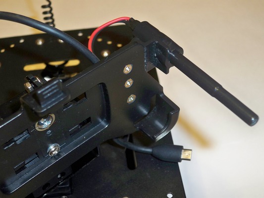
Now about the IR gun and IR receiver. The mount for the barrel of the gun is made of improvised means: for this role, the part from the half-toy clamp fit perfectly. I secured it to the left of the phone holder so that the gun did not interfere with the tilts of the robot’s head and the use of the “hardware” buttons of the smartphone if they were suddenly needed (the buttons are on the right). As I already wrote, the barrel is made of a telescopic antenna, and its sections are fixed with a shrink tube. I didn’t think too wisely with the IR receiver - in this form I only need it to conduct the Battle of the Battle, and then it can be removed (actually, a gun too). Therefore, I simply attached the receiver with double-sided tape on the back of the robot.
Well, a couple of words about electronics. To install a DC-DC converter, I bought a Proto Shield prototype card, and at the same time I soldered an IR receiver harness to cut off false positives. I also installed connectors for servo drives and a power connector for all my electronics. The 10-volt DC-DC converter output is directly connected to the Vcc and Gnd pins. Those. I do not use the Arduino Uno power connector. 5 volt DC-DC converter output is connected to the servo connectors. So it turned out four "floors" of boards. The fourth floor did not want to fit in the cart, I had to put small spacers to lift the top panel of the platform.
Combing
To release a robot, a face and, of course, a tail were required. I’m still a computer artist, so I only have Paint at hand. Somehow I painted four faces: happy, displeased, angry and killed to death. Then he corrected the management program to change moods. By the way, having tried both, I can say with confidence that programming is much easier. The tail is twisted from copper wire, stuffed into a heat shrink tubing and clamped between the back and the USB connector. Added sounds of gunshots and hits. It would be necessary still sounds under each mood.
In principle, with this one could already go out. But one more thing haunted me - the robot's handling.The implementation seems to be workable, but something was wrong. By tradition, the left joystick of the gamepad controls the movement. The right one is a review, i.e. head rotation. Deficiencies in the management were both there and there.
First, for those who do not know, a couple of words about joysticks. Gamepad joysticks at least under XNA give x and y coordinates in the range from -1 to +1. Point (0, 0) corresponds to the center position of the joystick. Moreover, the extreme positions of the joystick correspond to a circle with a radius equal to 1.
. , . . , . , , . x y 0 +1. (0, 0) (x, y). , , , x, . x . , , 0 ( ), , 90 , .
«» . , , X – , .
But one thing was not enough for ease of management. The values of the speeds throughout the above-described trigonometry varied from 0 to 1. I proportional to these values were transferred to values from 0 to 255 for setting the PWM on the motors. At small values, the engines only buzzed with different pitch, and then quite sharply picked up speed to the maximum. And intuitively it was perceived as discomfort when driving a cart. The output was in the addition of a non-linear relationship. For small values of the coordinate, for example, x, f (x) should grow rapidly. As x approaches 1, the growth of f (x) should slow down. The same for the y coordinate. The function of a circle with a center at the point (1, 0) and a radius of 1: f (x) = sqrt (2x - x ^ 2) suited me perfectly. After adding this transformation in both coordinates, the control became less sharp and more predictable.
And now about the right joystick and head rotation. My fault was that I converted the coordinates of the joystick into angles of rotation of the head proportionally. Those.the center position of the joystick corresponded to 90 degrees horizontally and 90 degrees vertically. This is the direction of gaze forward. I lie with the vertical because I introduced a software restriction on the angle of rotation vertically, and this was not 90 degrees, but the middle of the amplitude of the vertical deviation. But now it does not matter, we will consider 90 degrees, because my servos are rotated from 0 to 180 degrees. And what happened: at the coordinate of the joystick (1, 0), the head was turned to the right (0 degrees). At the coordinate (0, 1), the head is turned up (0 degrees). But if the joystick does not deviate horizontally or vertically, but diagonally, the head will no longer be able to get to zero degrees either through one or the other servo drive. The area of the joystick is a circle, so for example, the coordinate (1, 1) will not be available. Hence the conclusion:The circular area of the joystick with the center at the origin and a diameter of 2 must be “stretched” into a square area with the same center and side equal to 2. I solved this problem for the first half of the first quadrant (from 0 to 45 degrees), the other solutions were reflections. In short, the following happened:
x '= sqrt (x ^ 2 + y ^ 2)
y' = y * x '/ x
where (x', y ') are the new coordinates, stretched for a square, but only for the first half of the first quadrant.
Well, that's probably all. Having corrected controllability, I went to boast in the office.
Price
I would like to warn you if you want to enjoy the process of creating a robot, show imagination, boast to your friends before it is too late, I advise you to go to the heading “Plans and conclusion”. This section worries me.
First, at the cost of parts directly robot:
| Purchase date | price, rub. | Name |
| 10/21/2011 | 2,590 | 4 wheel platform |
| 10/21/2011 | 590 | Servo |
| 10/21/2011 | 1 990 | Matryoshka X (Arduino Uno + details for prototyping) |
| 10.26.2011 | 1,200 | Servo and bracket for it |
| 11/01/2011 | 0 | Battery packs 12V, 1100mAh 2 pieces (donated) |
| 11/01/2011 | 850 | Car holder for HTC Sensation |
| 11.11.2011 | 1,690 | USB Host Shield |
| 11/21/2011 | 690 | 2A Motor Shield |
| 11/21/2011 | 290 | Proto shield |
| 12/01/2011 | 93 | IR receiver TSOP3123 |
| 12/01/2011 | 13 | IR LED TSAL4400 |
| 12/01/2011 | 690 | Servo |
| 12/05/2011 | 886 | DC-DC converter TEN 8-1221 TRACO |
| all period | 1,000 | Small things (flux, wires, heat shrinkable tubes, batteries, etc.) |
| Total | 12,572 |
That's the amount. Moscow prices. True, the details can be ordered in Chinese online stores. There prices differ amazingly: it turns out to be two or even three times cheaper. But you have to wait a long time. I had little time, although, I must admit, I would not have suffered.
Now, what else did I buy or have already had and without what the robot will not go:
| Purchase date | price, rub. | Name |
| 10.29.2011 | 1,290 | Gamepad XBOX 360 |
| 11/25/2011 | 3,850 | Universal IMAX B5 Charger |
| long | 18,900 | HTC Sensation (average price in Moscow on 12/19/2011 on Yandex Market) |
Plans and conclusion
After two months of midnight work, when I went through everything described above, my wife asked me: “No, I understand everything, but that you just can’t buy a radio-controlled machine?”
Skip the paragraph.
Yes. So far, what I have early to call a robot. I understand it. , . , , . .
, . , , «» «» , , , , . . , .
, , - .
UPD: code.google.com. , : robot-mitya .
I opened to view the entire source code. Here are all three levels of robot programming: a sketch for Arduino, an Android application and a Windows application. Subversion is used as a version control system. The tag folder contains a fully working release version 1.0.0. I checked its operation from scratch by downloading project source codes from the server, compiling them and executing them on the robot. In the Trunk folder, as always, the current branch of the project.
Arduino-sketch is written on IDE version arduino-0022. The IDE version with the libraries I use is uploaded to the downloads section .
When writing an Android application, the Eclipse IDE for Java Developers version of Indigo Service Release 1 with the Checkstyle code analysis plugin installed was used. The only concession that I allowed myself in the Checkstyle settings is an increase in the maximum string length from 80 to 160 characters. The remaining settings are left unchanged.
Microsoft Visual C # 2010 Express was used to develop a Windows application. For the analysis of the quality of the code used StyleCop. Express Studio version does not support embedding extensions, but the use of StyleCop is possible due to the possibility of its integration with MSBuild. The topic is wonderfully described in the article StyleCop & C # Express .
Good luck!
Source: https://habr.com/ru/post/135043/
All Articles