Networks for the smallest. Part zero. Planning
All issues
8. Networks for the smallest. Part Eight BGP and IP SLA
7. Networks for the smallest. Part Seven. VPN
6. Networks for the smallest. Part six. Dynamic routing
5. Networks for the smallest: Part Five. NAT and ACL
4. Networks for the smallest: Part Four. STP
3. Networks for the smallest: Part Three. Static routing
2. Networks for the smallest. Part two. Switching
1. Networks for the smallest. Part one. Connection to the equipment cisco
0. Networks for the smallest. Part zero. Planning
This is the first article in the series “Networks for the smallest”. Thegluck and I thought for a long time where to start: routing, VLANs, hardware configuration.
In the end, we decided to start with the fundamental and, one can say, the most important thing: planning. Since the cycle is designed for completely beginners, then we will go all the way from beginning to end.
It is assumed that you, at least, read about the OSI reference model (the same in English ), the TCP / IP protocol stack ( English ), know about the types of existing VLANs (I strongly recommend this article to be read), about most now popular port-based VLAN and IP addresses (in more detail ). We understand that for newbies “OSI” and “TCP / IP” are scary words. But do not worry, not to intimidate you, we use them. This is what you will have to meet every day, so during this cycle we will try to reveal their meaning and attitude to reality.
')
Let's start with the problem statement. There is a certain company engaged, say, in the production of elevators going only upwards, and therefore it is called Lift Me Up LLC. They are located in the old building on Arbat, and the rotten wires stuck into the burned and burned switches of the 10Base-T times do not expect connection of new servers using Gigabit cards. So they have a catastrophic need for network infrastructure and money for chickens, which do give you the opportunity to make unlimited choices. This is a wonderful dream of any engineer. And you yesterday passed the interview and in a difficult struggle by right received a network administrator position. And now you are the first and only one of its kind. Congratulations! What's next?
It should be somewhat specific to the situation.
- At the moment, the company has two offices: 200 squares on the Arbat for workplaces and server. There are several providers. Another on the ruble.
- There are four user groups: accounting (B), financial and economic department (FEI), production and technical department (PTI), other users (D). And there are also servers (C), which are placed in a separate group. All groups are demarcated and do not have direct access to each other.
- Users of groups C, B and FD will only be in an office on Arbat, VET and D will be in both offices.
Having estimated the number of users, necessary interfaces, communication channels, you are preparing a network diagram and an IP plan.
When designing a network, you should try to adhere to a hierarchical model of the network , which has many advantages compared to a “flat network”:
- easier understanding of networking
- the model implies modularity, which means that it’s easy to build capacity exactly where you need it
- easier to find and isolate the problem
- increased fault tolerance by duplicating devices and / or connections
- distribution of functions to ensure the health of the network for various devices.
According to this model, the network is divided into three logical levels: the network core (Core layer: high-performance devices, the main purpose is fast transport), the distribution level (Distribution layer: ensures the application of security policies, QoS, aggregation and routing in VLAN, defines broadcast domains) and access level (Access-layer: as a rule, L2 switches, purpose: connecting end devices, marking traffic for QoS, protection from network rings (STP) and broadcast storms, providing power for PoE devices).
On such a scale as ours, the role of each device is blurred, but the network can be logically divided.
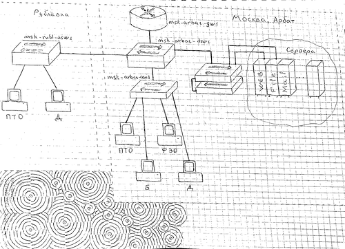
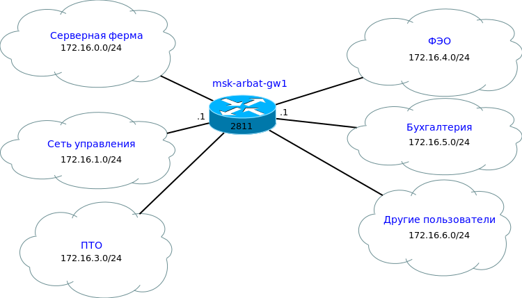
We make an approximate scheme:
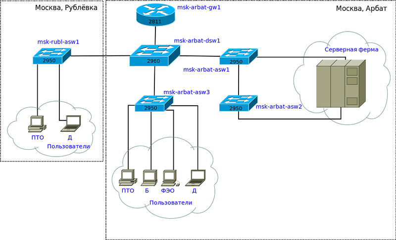
On the presented scheme, the core (Core) will be the 2811 router, the 2960 switch is referred to the distribution level (Distribution), since all VLANs are aggregated into a common trunk on it. Switches 2950 will be access devices. They will connect end users, office equipment, server.
We will name the devices as follows: the abbreviated name of the city ( msk ) - geographical location (street, building) ( arbat ) - the role of the device in the network + serial number.
According to their roles and location, choose the hostname :
Router 2811: msk-arbat-gw1 (gw = GateWay = gateway)
Switch 2960: msk-arbat-dsw1 (dsw = Distribution switch)
Switches 2950: msk-arbat-aswN, msk-rubl-asw1 (asw = Access switch)
Network documentation
The entire network must be strictly documented: from the concept to the name of the interface.
Before proceeding with the configuration, I would like to provide a list of the necessary documents and actions:
• Network diagrams L1, L2, L3 in accordance with the levels of the OSI model (Physical, channel, network)
• IP Addressing Plan = IP Plan.
• VLAN list
• Interface signatures
• List of devices (for each, you should specify: the model of the piece of iron, the installed version of IOS, the amount of RAM \ NVRAM, the list of interfaces)
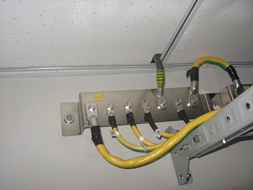
• Labels on cables (from where and where it goes), including on power and ground cables and devices
• Uniform regulations defining all the above parameters and others.
Bold highlighted what we will monitor in the framework of the simulator. Of course, all network changes need to be made to the documentation and configuration so that they are up to date.
Speaking about tags / labels on cables, we mean this:
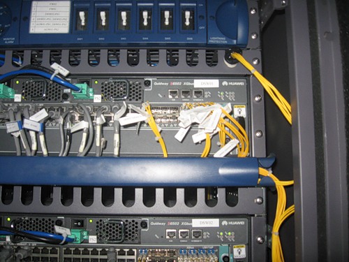
In this photo you can clearly see that each cable is marked, the value of each machine on the panel in the rack, as well as each device.
Prepare the documents we need:
VLAN list
| VLAN No. | VLAN name | Note |
|---|---|---|
| one | default | Not used |
| 2 | Management | To control devices |
| 3 | Servers | For server farm |
| 4-100 | Reserved | |
| 101 | PTO | For VET users |
| 102 | FEO | For users of FDI |
| 103 | Accounting | For accounting users |
| 104 | Other | For other users |
Each group will be allocated in a separate vlan. Thus, we will restrict broadcast domains. We also introduce a special VLAN for device management.
VLAN numbers 4 to 100 are reserved for future needs.
IP plan
| IP address | Note | VLAN |
|---|---|---|
| 172.16.0.0/16 | ||
| 172.16.0.0/24 | Server farm | 3 |
| 172.16.0.1 | Gateway | |
| 172.16.0.2 | Web | |
| 172.16.0.3 | File | |
| 172.16.0.4 | ||
| 172.16.0.5 - 172.16.0.254 | Reserved | |
| 172.16.1.0/24 | Control | 2 |
| 172.16.1.1 | Gateway | |
| 172.16.1.2 | msk-arbat-dswl | |
| 172.16.1.3 | msk-arbat-aswl | |
| 172.16.1.4 | msk-arbat-asw2 | |
| 172.16.1.5 | msk-arbat-asw3 | |
| 172.16.1.6 | msk-rubl-aswl | |
| 172.16.1.6 - 172.16.1.254 | Reserved | |
| 172.16.2.0/24 | Point-to-Point Network | |
| 172.16.2.1 | Gateway | |
| 172.16.2.2 - 172.16.2.254 | Reserved | |
| 172.16.3.0/24 | VET | 101 |
| 172.16.3.1 | Gateway | |
| 172.16.3.2 - 172.16.3.254 | User pool | |
| 172.16.4.0/24 | FEO | 102 |
| 172.16.4.1 | Gateway | |
| 172.16.4.2 - 172.16.4.254 | User pool | |
| 172.16.5.0/24 | Accounting | 103 |
| 172.16.5.1 | Gateway | |
| 172.16.5.2 - 172.16.5.254 | User pool | |
| 172.16.6.0/24 | Other users | 104 |
| 172.16.6.1 | Gateway | |
| 172.16.6.2 - 172.16.6.254 | User pool |
The allocation of subnetworks is in general arbitrary, corresponding only to the number of nodes in this local network, taking into account possible growth. In this example, all subnets have a standard / 24 mask (/24=255.255.255.0) - they are often used in local networks, but not always. We advise you to read about the classes of networks . In the future, we turn to classless addressing (cisco). We understand that references to technical articles in Wikipedia are moveton, but they give a good definition, and we will try in turn to transfer this to the picture of the real world.
By a Point-to-Point network, we mean connecting one router to another in point-to-point mode. Usually, addresses are taken with a mask of 30 (returning to the topic of classless networks), that is, containing two node addresses. Later it becomes clear what is at stake.
Equipment connection plan by ports
Of course, there are now switches with a bunch of 1Gb Ethernet ports, there are 10G switches, 40Gb are on advanced operator hardware costing thousands of dollars, 100Gb is being developed (and even there are rumors that have been commercially available). Accordingly, you can choose in the real world switches and routers according to your needs, without forgetting about the budget. In particular, a gigabit switch can now be purchased inexpensively (20-30 thousand) and this is with a reserve for the future (if you are not a provider, of course). A router with gigabit ports is already significantly more expensive than with 100Mbps ports, but it is worth it, because FE models (100Mbps FastEthernet) are outdated and their bandwidth is very low.
But in the programs of emulators / simulators that we will use, unfortunately, there are only unpretentious models of equipment, therefore, when modeling the network, we will build on what we have: cisco2811 router, cisco2960 and 2950 switches.
| Device name | Port | Title | VLAN | |
|---|---|---|---|---|
| Access | Trunk | |||
| msk-arbat-gw1 | FE0 / 1 | Uplink | ||
| FE0 / 0 | msk-arbat-dsw1 | 2,3,101,102,103,104 | ||
| msk-arbat-dsw1 | FE0 / 24 | msk-arbat-gw1 | 2,3,101,102,103,104 | |
| GE1 / 1 | msk-arbat-asw1 | 2.3 | ||
| GE1 / 2 | msk-arbat-asw3 | 2,101,102,103,104 | ||
| FE0 / 1 | msk-rubl-asw1 | 2,101,104 | ||
| msk-arbat-asw1 | GE1 / 1 | msk-arbat-dsw1 | 2.3 | |
| GE1 / 2 | msk-arbat-asw2 | 2.3 | ||
| FE0 / 1 | Web server | 3 | ||
| FE0 / 2 | File server | 3 | ||
| msk-arbat-asw2 | GE1 / 1 | msk-arbat-asw1 | 2.3 | |
| FE0 / 1 | Mail server | 3 | ||
| msk-arbat-asw3 | GE1 / 1 | msk-arbat-dsw1 | 2,101,102,103,104 | |
| FE0 / 1-FE0 / 5 | PTO | 101 | ||
| FE0 / 6-FE0 / 10 | FEO | 102 | ||
| FE0 / 11-FE0 / 15 | Accounting | 103 | ||
| FE0 / 16-FE0 / 24 | Other | 104 | ||
| msk-rubl-asw1 | FE0 / 24 | msk-arbat-dsw1 | 2,101,104 | |
| FE0 / 1-FE0 / 15 | PTO | 101 | ||
| FE0 / 20 | administrator | 104 | ||
Why VLANs are distributed in this way will be explained in the following sections.
Excel-document with a list of VLAN, IP, ports
Network diagrams
Based on these data, you can create all three network diagrams at this stage. To do this, you can use Microsoft Visio, any free application, but with reference to its format, or graphics editors (you can also by hand, but it will be difficult to keep up to date :)).
Not propaganda open source for, but a variety of means for the sake of, we use Dia. I consider it one of the best applications for working with schemes under Linux. There is a version for Windows, but, unfortunately, there is no compatibility in any.
L1

That is, on the L1 diagram, we reflect the physical devices of the network with port numbers: what is connected to where.
L2
On the L2 scheme, we specify our VLANs

L3
In our example, the scheme of the third level was rather useless and not very visual, due to the presence of only one routing device. But over time, it will acquire more details.
Dia files with network diagrams: L1 , L2 , L3
As you can see, the information in the documents is redundant. For example, VLAN numbers are repeated both in the scheme and in the plan by ports. Here, as if someone on that much. As you prefer, do so. Such redundancy makes it difficult to update in the event of a configuration change, because you need to fix it in several places at once, but on the other hand, it makes understanding easier.
We will return to this first article more than once in the future, just as you will always have to go back to what you originally planned.
Actually, the task is for those who are just starting to learn and are ready to make efforts for this: read a lot about proprietary, ip-addressing, find Packet Tracer and GNS3 programs.
As for the fundamental theoretical knowledge, we advise you to start reading Cisco press: one , two , three (Russian). This is something that you absolutely need to know.
In the next part, everything will be in an adult way, with the video, we will learn to connect to the equipment, deal with the interface and tell you what to do to a careless admin who has forgotten the password.
PS Thanks to the co-author of the article - thegluck user.
PPS For those who have something to ask, but do not have the opportunity to ask their question here, you are welcome to learn
Source: https://habr.com/ru/post/134892/
All Articles