"Ticking" clock with an alarm clock on the Atmega48 microcontroller
Description
These alarm clocks are based on a real-time clock chip, which allows them to work from a backup power source in the absence of the main one. The specified alarm time and mode of operation is stored in the non-volatile memory of the microcontroller. Display mode - 24 hour. They contain imitation of “tick”. Indication of time and operating modes is carried out by means of LED indicators.
Principle of operation
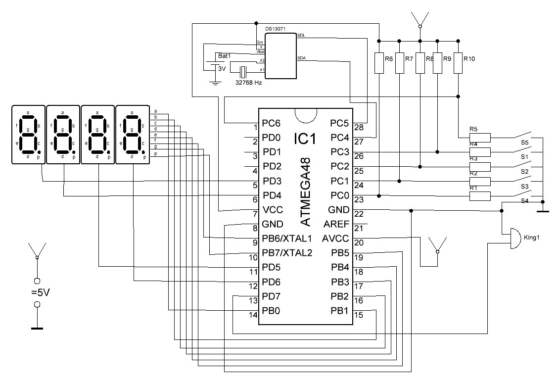
The basis of these clocks is the DS1307 microcircuit - a real-time clock that communicates with the controlling controller via the I2C interface. The time is indicated by 4 7-segment indicators operating in dynamic mode. Time is entered and adjusted by 5 buttons: "+ minutes", "+ hours", "setting", "alarm clock" and "reset". The alarm sound signal is output through a standard piezo emitter and is a 1 kHz signal with a second pause.
Atmega48 was chosen as the controlling microcontroller due to its availability and the availability of the necessary peripherals on board (even with an excess). The DS1307 real-time clock is connected to the I2C hardware outputs of the control microcontroller. The DS1307 works autonomously (in case of power failure of the main controller) using a 3V lithium backup battery, which will last for several years due to the low power consumption of the chip.
Let us consider the control program in more detail:
')
The program works on the principle of a flag-timer automaton: all states and events are represented as corresponding flags, executed in interrupts of the corresponding timer 1c, 1ms and 263.17ms. The program uses 2 hardware timers.
Interrogation of the clock chip and pressing the buttons is carried out at intervals of 263.17 ms The 1ms interval is used to generate a ringing sound signal, and 1c - to modulate it. The second interval also controls the flashing of the dot in the 2nd digit of the indicator, separating the hours and minutes and also serving the formation of a “tick”.
Consider the concept of hours.
Designations and denominations:
S4 - Increase hours
S3 - Increase minutes
S2 - Installation
S1 - Enable Alarm Clock
S5 - Reset
R6-R10 - 10k
R1-R5 - 510th
Power supply - 5 volts.
Setup and use
Correctly assembled clocks do not need additional configuration. You only need to set the current time and alarm.
Setting the current time is as follows:
1) Use the S1 and S2 buttons to set the current time (the dot between the digits does not blink)
2) Start the clock with the S3 button
Setting the alarm:
1) Press S3 and make sure that the dot in the 1st bit is lit.
2) Set the call time using the S1 and S2 buttons
3) Enable the call with the S4 button
Additional features:
Enable tick - hold S4 and press S2 until characteristic sounds appear. It also turns off.
Displaying minutes and seconds - hold S4 and press S1. If you then press S3, the seconds will be reset to 00. Return is the same combination.
Appendix: Source code (in assembler) + hex for microcontroller atmega48 + model in Proteus .
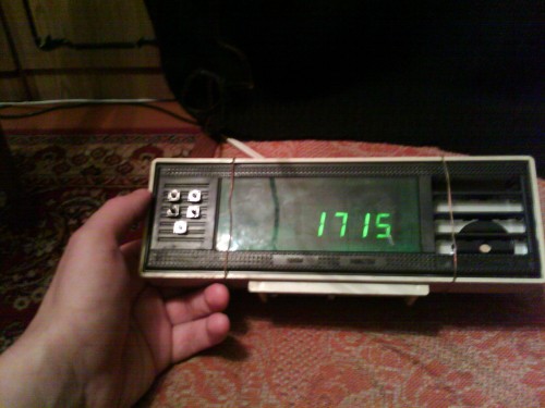
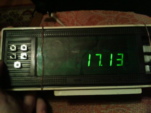
Photo and video hours
The watches are assembled in the case of non-working "electronics".
Source: https://habr.com/ru/post/134879/
All Articles