Cycling with turn signals
I want to share with the habrasoobschestvom interesting project. It will not only help to increase safety in the absence of bicycle lanes, but it will also look amazingly alive. And yes, I dare to reassure you, in the near future I will no longer disturb you with translations. * approx. translator
“I understood one simple truth. It is to do miracles with her own hands. ”
© A. Green "Scarlet Sails"
')
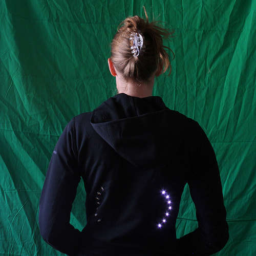
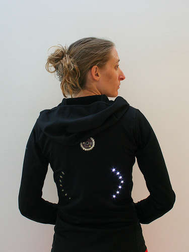
In this guide, I will tell you how to make a blouse with turn signals so that when cycling, people know exactly when (and where) you will turn. In the end, you get a comfortable and durable jacket, which, in addition, can be washed, since materials allow. Enjoy!
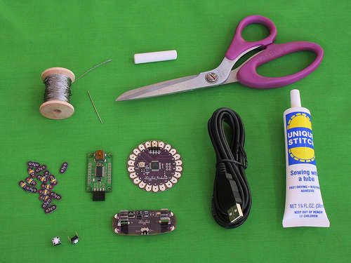
We will need:
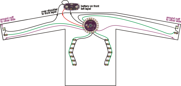


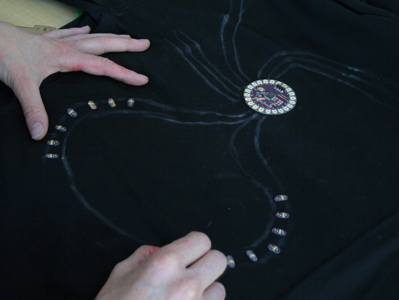
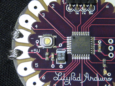
The main task is to decide where and how the construction details should be located so that the conductors intersect as little as possible. Before the beginning of the actual work is to develop a sketch. On the photo above are sketches for my jacket. The power connection (+) is shown in red, the ground (-) is black, the LED is green, and the switches are purple.
I strongly recommend placing the power board near the LilyPad Arduino. Otherwise, you risk the fact that LilyPad Arduino can not earn at all.
Why? It is just that conductive filaments do not have the usual resistance (in a used filament, the resistance is 46 Ω / m). Depending on what parts you use in your design, the current can be 0.05A. Ohm's law states that the voltage drop on conductive materials is equal to the resistance of this material to the current that flows through it.
For example, if the power supply from LilyPad is placed at a distance of 0.3m, the voltage drop is 1.4 V. It turns out that at a voltage of 5 V on the battery, only 3.6 V will reach the LilyPad, and when its value reaches 3.3 In, LilyPad will not run at all. In general, the resistance when connecting power to the LilyPad should be no more than 10 ohms.
But do not immediately get upset by the foregoing! Simply place the power and LilyPad at an appropriate distance.
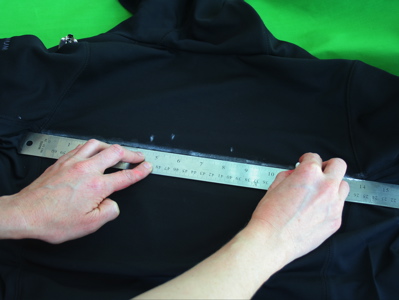
To transfer your sketch to a jacket, use chalk or other time markings. Using double-sided tape, glue the LilyPad to where the board will end up. This will help to evaluate the picture as a whole and it will be easier to finally sew the board onto the jacket.


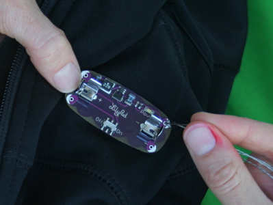
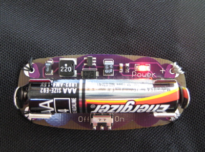
Remove the back cover from the power board and remove the metal trim. To do this, you can use small pliers as in the photo, well, or use scissors.
So, the most important thing is to firmly fix the battery on the fabric. Personally, I recommend sticking or stitching it before continuing on. By the way, you can glue or sew something under it to reduce contact with the stretching fabric.
If you decide to “pump” thin or strongly stretching fabric ... Reconsider your choice! It will be much easier to work with a dense and non-expandable material. If you are still determined to continue working with a thin fabric, think carefully about the location of the power board, because this is the hardest part of the design. So fasten it somewhere, where it will not strongly pull off the material. And yes, in this case without options - be sure to glue or sew something under the power board.
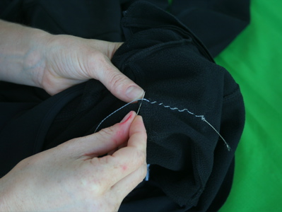
If you have never held a needle with a string in your hands, check out this instruction here ( it’s in bourgeois, of course, but there are a lot of clear pictures * ). Cut 0.9-1.2 meters of conductive thread. Now thread the needle. Tie a knot at the end, but not too close to the end of the thread, otherwise the knot will quickly untie.
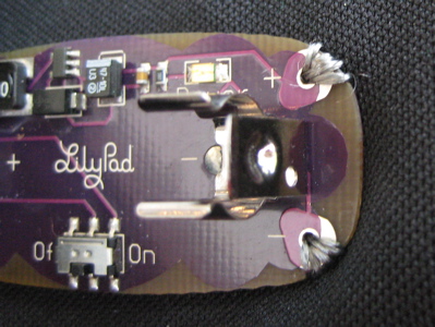
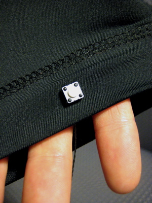
Sew the power board, starting from the back, as close as possible to the + board. Make a few stitches so that it holds better, and the contact between the feed and the thread was good. I recommend to make 5 stitches, in any case, do stitches until the needle hardly passes through the hole.

After stitching + power contact, do neat stitches in the direction of the + LilyPad contact. I sewed to the fleece lining so that the seams were not visible on the front side of the jacket. Establish a connection with the LilyPad contact in the same way as with the contact of the power board. When complete the procedure, treat the nodes with factory glue.

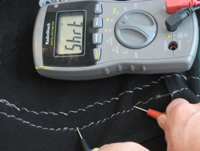
Uncover the multimeter and put it in the resistance measurement mode. Measure the resistance at 2 sites: from + power to + LilyPad and from - power to - LilyPad. If the resistance of any of these areas will be more than 10 ohms, you will have to reconnect the connection.
Put the AAA battery in the power board and turn it on. The red diode should light up. If this does not happen, and you are sure that the switch is in the correct position, quickly remove the battery and check the connection for a short circuit. As a matter of fact, you can check for a short circuit with a multimeter.
And check for resistance between + and -. If it is less than 10 kOhm, congratulations, you have a short circuit. Then you should find it and fix it.
If the power board is okay, go get LilyPad. Each time you press the switch, the light should flash on it. After all connections are working, turn off the power and remove the battery.
Well, now your sweater is jam-packed with non-insulated conductive seams. There is nothing terrible when the jacket is dressed on you, because the body will not allow the wires to close between themselves. But you will not just stand like a mannequin. If you take off the jacket or just move, there is a high probability of a short circuit between the wires. To prevent this, use a blown fabric dye (or other insulating material). Of course, it is worth to isolate only if you are sure of the connection. So this step should be carried out at that moment, when you see fit.


Use the same technique that was used to power the LilyPad. Connect + the contacts of the LEDs to turn left with 9 contacts of the LilyPad, and to turn right with 11 contacts of the LilyPad. Now connect everything - the contacts of the LEDs and attach them to the - contact or to the 10th contact of the LilyPad. If you have any misunderstandings with the connection, refer to the sketch above.
Do not forget to cover all the nodes with glue to avoid breaking the connection. And also do not allow short circuit. After connecting the LEDs, make sure that the positive connections do not touch the negative ones.
Download the test program in LilyPad. Here is my text:
, , Arduino window. , , .
, .

, , . . .
, , «» .


. «» LilyPad, , , LilyPad. + 6 12 . : — 4 — . — .

, . .
, . , . + LilyPad ( , 5 3 ), — — . , - .
: .


, , ! -. …
: , 15 - . , , . , « », . , , , . , .
, Arduino window LilyPad. , . , .
, … !
“I understood one simple truth. It is to do miracles with her own hands. ”
© A. Green "Scarlet Sails"
')
In this guide, I will tell you how to make a blouse with turn signals so that when cycling, people know exactly when (and where) you will turn. In the end, you get a comfortable and durable jacket, which, in addition, can be washed, since materials allow. Enjoy!
Materials
We will need:
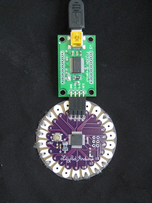
- LilyPad Arduino board
- module converter USB to Serial FTDI Basic Breakout 3.3V
- mini usb cables
- Power Board for LilyPad Arduino
- 16 LED LilyPad
- 2 miniature pushbuttons
- conductive thread reel
- digital multimeter with “ringing”
- proper jacket
- a needle or even two, a piece of chalk, factory glue and a ruler
- scissors
- double sided tape
- sewing machine
Design
Placement of parts
The main task is to decide where and how the construction details should be located so that the conductors intersect as little as possible. Before the beginning of the actual work is to develop a sketch. On the photo above are sketches for my jacket. The power connection (+) is shown in red, the ground (-) is black, the LED is green, and the switches are purple.
Important about nutrition
I strongly recommend placing the power board near the LilyPad Arduino. Otherwise, you risk the fact that LilyPad Arduino can not earn at all.
Why? It is just that conductive filaments do not have the usual resistance (in a used filament, the resistance is 46 Ω / m). Depending on what parts you use in your design, the current can be 0.05A. Ohm's law states that the voltage drop on conductive materials is equal to the resistance of this material to the current that flows through it.
For example, if the power supply from LilyPad is placed at a distance of 0.3m, the voltage drop is 1.4 V. It turns out that at a voltage of 5 V on the battery, only 3.6 V will reach the LilyPad, and when its value reaches 3.3 In, LilyPad will not run at all. In general, the resistance when connecting power to the LilyPad should be no more than 10 ohms.
But do not immediately get upset by the foregoing! Simply place the power and LilyPad at an appropriate distance.
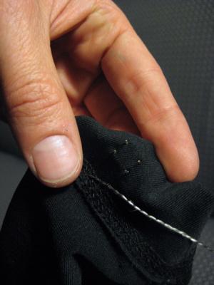
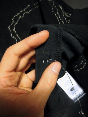
We transfer the sketch on clothes
To transfer your sketch to a jacket, use chalk or other time markings. Using double-sided tape, glue the LilyPad to where the board will end up. This will help to evaluate the picture as a whole and it will be easier to finally sew the board onto the jacket.
We sew the power board and LilyPad to the sweater
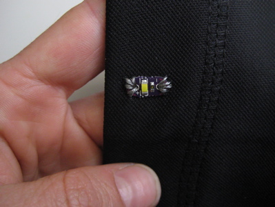
For starters, disassemble the power board
Remove the back cover from the power board and remove the metal trim. To do this, you can use small pliers as in the photo, well, or use scissors.
Fasten the battery to the fabric
So, the most important thing is to firmly fix the battery on the fabric. Personally, I recommend sticking or stitching it before continuing on. By the way, you can glue or sew something under it to reduce contact with the stretching fabric.
If you decide to “pump” thin or strongly stretching fabric ... Reconsider your choice! It will be much easier to work with a dense and non-expandable material. If you are still determined to continue working with a thin fabric, think carefully about the location of the power board, because this is the hardest part of the design. So fasten it somewhere, where it will not strongly pull off the material. And yes, in this case without options - be sure to glue or sew something under the power board.
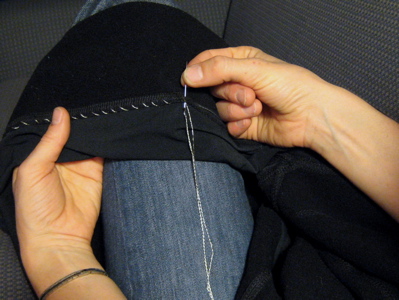
We sew + contact the power board to the jacket
If you have never held a needle with a string in your hands, check out this instruction here ( it’s in bourgeois, of course, but there are a lot of clear pictures * ). Cut 0.9-1.2 meters of conductive thread. Now thread the needle. Tie a knot at the end, but not too close to the end of the thread, otherwise the knot will quickly untie.
Sew the power board, starting from the back, as close as possible to the + board. Make a few stitches so that it holds better, and the contact between the feed and the thread was good. I recommend to make 5 stitches, in any case, do stitches until the needle hardly passes through the hole.
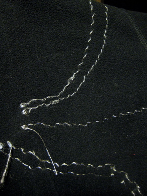
We sew from the battery to the LilyPad and terminate the connection
After stitching + power contact, do neat stitches in the direction of the + LilyPad contact. I sewed to the fleece lining so that the seams were not visible on the front side of the jacket. Establish a connection with the LilyPad contact in the same way as with the contact of the power board. When complete the procedure, treat the nodes with factory glue.
Check the resulting connection
Measure resistance
Uncover the multimeter and put it in the resistance measurement mode. Measure the resistance at 2 sites: from + power to + LilyPad and from - power to - LilyPad. If the resistance of any of these areas will be more than 10 ohms, you will have to reconnect the connection.
Put the AAA battery in the power board and turn it on. The red diode should light up. If this does not happen, and you are sure that the switch is in the correct position, quickly remove the battery and check the connection for a short circuit. As a matter of fact, you can check for a short circuit with a multimeter.
And check for resistance between + and -. If it is less than 10 kOhm, congratulations, you have a short circuit. Then you should find it and fix it.
If the power board is okay, go get LilyPad. Each time you press the switch, the light should flash on it. After all connections are working, turn off the power and remove the battery.
Insulate power and ground
Well, now your sweater is jam-packed with non-insulated conductive seams. There is nothing terrible when the jacket is dressed on you, because the body will not allow the wires to close between themselves. But you will not just stand like a mannequin. If you take off the jacket or just move, there is a high probability of a short circuit between the wires. To prevent this, use a blown fabric dye (or other insulating material). Of course, it is worth to isolate only if you are sure of the connection. So this step should be carried out at that moment, when you see fit.
Sewing turn signals
Turn right, turn left
Use the same technique that was used to power the LilyPad. Connect + the contacts of the LEDs to turn left with 9 contacts of the LilyPad, and to turn right with 11 contacts of the LilyPad. Now connect everything - the contacts of the LEDs and attach them to the - contact or to the 10th contact of the LilyPad. If you have any misunderstandings with the connection, refer to the sketch above.
Do not forget to cover all the nodes with glue to avoid breaking the connection. And also do not allow short circuit. After connecting the LEDs, make sure that the positive connections do not touch the negative ones.
Checking turn signals
Download the test program in LilyPad. Here is my text:
int ledPin = 13; // the LED on the LilyPad
int leftSignal = 9; // my left turn signal is attached to petal 9
int rightSignal = 11; // my right turn signal is attached to petal 11
int signalLow = 10; // the - sides of my signals are attached to petal 10

void setup()
{
 pinMode(ledPin, OUTPUT); // sets the ledPin to be an output
 pinMode(leftSignal, OUTPUT); // sets the leftSignal petal to be an output
 pinMode(rightSignal, OUTPUT); // sets the rightSignal petal to be an output
 pinMode(signalLow, OUTPUT); // sets the signalLow petal to be an output
 digitalWrite(signalLow, LOW); // sets the signalLOW petal to LOW (-)
}

void loop() // run over and over again
{
 delay(1000); // wait for 1 second
 digitalWrite(leftSignal, LOW); // turn the left signal off
 delay(1000); // wait for 1 second
 digitalWrite(rightSignal, HIGH); // turn the right signal on
 delay(1000); // wait for 1 second
 digitalWrite(rightSignal, LOW); // turn the right signal off
 delay(1000); // wait for 1 second
}
, , Arduino window. , , .
, .
, , . . .
, , «» .
. «» LilyPad, , , LilyPad. + 6 12 . : — 4 — . — .
, . .
, . , . + LilyPad ( , 5 3 ), — — . , - .
: .
, , ! -. …
: , 15 - . , , . , « », . , , , . , .
, Arduino window LilyPad. , . , .
, … !
Source: https://habr.com/ru/post/134175/
All Articles