Using DSL in Visual Studio
Introduction
Previously, I never thought about developing tools that simplify development in Visual Studio, and often created various third-party utilities to help myself in development. But, as usual, the turning point has come.
One day, the challenge was to develop a platform on the basis of which it would be necessary to develop specialized solutions.
I wanted to simplify the development of solutions on the platform as much as possible, while not reducing the possibility of flexible configuration.
There were two main ways to solve the problem:
- Develop your own decision making tools
- Create support tools built into the development environment.
Own tools
When using this approach, it would be possible in the future to do almost without coding. This undoubtedly simplifies and accelerates the development of the solution, and also reduces the possibility of errors (unless of course everything is done cleanly).
But the main difficulty, which appears to the developer of the tools, is to provide as much as possible all the necessary features that may be required.
In each solution, there are not trivial tasks that you couldn’t think about at the stage of creating tools. Also, when creating universal tools, there is an increase in their complexity, which affects the time of creation, as well as the complexity of use.
Visual Studio Aids
When using tools, you automate the necessary basic code as much as possible, and allow you to expand the functionality of the system.
But to use this approach, solution developers should have a higher professional level.
My choice
After weighing all the pros and cons that I could think of, I decided to opt for the second option. It was a novelty for me and very fascinated.
Next, I will try to describe the basics of creating tools for Visual Studio 2010 using DSL. Perhaps this will push you to further independent study of this area.
')
Pre
Before we begin, we need to download and install the following distributions:
Formulation of the problem
To begin with, we need to come up with an example, on the basis of which it would be possible to present both the main possibilities and show how this mechanism can be effective for solving everyday tasks.
At first, this task seemed elementary, but when I was lost in thought, I realized that everything was not so simple. After spending some time in meditation, I still came up with it.
I propose to create a model to assist in developing client-server applications, at the level of creating WCF services. Of course, we will not put a strong emphasis on the technical side of WCF, but take it as an object model.
Creating a project and debugging it
Having set a task for ourselves, without much thought, we will create our own project.
As always, when starting work, we launch our beloved Visual Studio 2010.
Go to the project creation window and select the project type Domain-Specific Language Designer .

Then the Wizard will offer us to choose the type of module being created. Choose MinimalLanguage. In this type of project the minimum number of pre-created elements, which will allow us to get rid of them faster.

Next you need to set the extension for our file. With this extension, we will add our files to projects.
The last contribution is a summary of the project being created.
After we click Finish, our project opens with pre-created elements, this is done in order to show us an example.
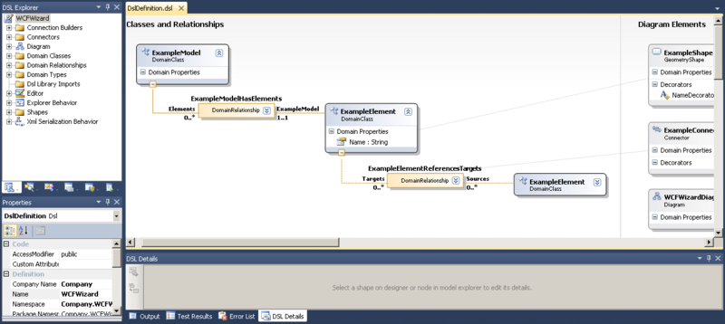
You can immediately compile the project and try to test it.
For testing and debugging projects of this type, a debugging studio is used. If you click to run, or run with debugging, then you will have an additional studio where a test copy of your project file will be created.
Try experimenting with this example.
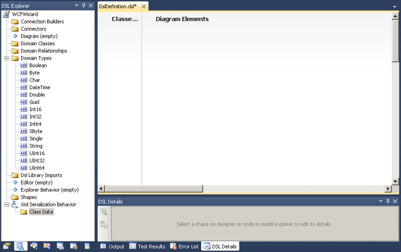
Clean all
All that we have, not really useful to us, so remove everything that was added automatically.
Go to DSL Explorer and remove everything from there, except for the standard types in Domain Types.
The result should be the following:
We describe the main Toolbox objects.
Domain Class is a data object.
Named Domain Class - a named data object that contains the Name property. Further, the system will interpret this property as the name of the object, and will automatically generate its unique name.
Geometry Shape - a visual representation that is used to visualize data objects in a diagram
Compartment Shape - also that Geometry Shape, only has a different look.
Embedding Relationship - connects objects with a belonging affiliation
Reference Relationship - binds objects with the type object reference
Inheritance - parental type of connection, that is, the inheritance of one object from another
Connector - Relationship Visualizer
Diagram Element Map - used to connect objects and links with their visual presentation
Creating basic objects and their mappings
Before you start creating our direct objects, you need to create preparatory elements:
- Designer - a designer to visualize our objects. In the DSL Explorer , we will create an Editor object. It is necessary to set in it anew the extension for our project (This is the FileExtension property), which let it be “wcfw”.
- Diagram is the main visualization element that represents our objects. Let's call it “WCFDiagram”.
- You need to create a root element ( Domain Class ) to which you will need to configure the Editor created earlier (This is the Root Class property) and Diagram (This is the Class Represented property). Give the name to our root element “WCFCollection”.
- Explorer Behavior - something like DSL Explorer , which will be displayed when working with a file of our type.
This is a minimal list of what needs to be done so that our file is saved and the project can be compiled. But before compiling it is necessary to regenerate the code according to the changes made to the file. In order to do this, you need to click the Transform All Templates button in Solution Explorer .

All code is generated by * .tt files (which describe the T4-transformation), which lie in the GeneratedCode folders in the Dsl and DslPackage projects . After the new objects have been generated, you can collect our projects and even launch them. It starts all the same debugging studio, with the same project. The project added a file that related to the pilot project, so they can all be deleted. Add your own file type (as well as any type), finding it by the name of WCFWizard.
Creating an object describing the "service"
Let's start by creating the “service” object. To do this, drag the Named Domain Class element from the Toolbox and name it “WCFService”. We automatically have an object with the property Name, which has the flag Is Element Name , which says that this property is the name of the object.
It is time to describe the basic properties of the Domain Class and Named Domain Class objects.
| Property name | Description |
| Access Modifier | Level of access to the generated class. |
| Base class | Base class. We can select another created object here, and then in the generated code the current class will be inherited from the class specified by the base class. |
| Custom attributes | This is where additional attributes are attached to the object. |
| Description | Description of the object. |
| Display name | The display name of the object that the user will see. |
| Generates double derived | If True is true, then two classes are generated (and usually one), one is abstract, with all that is needed, and the second is generating a partial class that is empty inside. This allows you to further redefine the virtual functions that are declared in the base classes. |
| Has Custom Constructor | If it is True, then you will need to define the necessary constructors in your extension class. This is useful when you need to perform additional actions when creating an object. |
| Inheritance modifier | Allows you to make your class abstract, or so that it can not be inherited. |
| Name | The name of the object with this name will generate a class. |
| Namespace | The namespace for your class. |
For now, leave all fields by default. And we will describe additional properties of the Domain Property element.
| Property name | Description |
| Getter access modifier | Permissions to read the property. |
| Setter Access Modifier | Permissions to write property. |
| Is UI Read Only | Whether to show the property as read only. |
| Is browsable | Whether to show the property to the user. |
| Default Value | Default field values. |
| Element Name Provider | The external type that will supply the values for the property. The property must have an Is Element Name value equal to True . Allows you to generate unique names for a specific algorithm. |
| Is Element Name | Whether a property is an object name. If true, the initial value will be created unique. |
| Kinda | The type of field that affects its storage:
|
| Type | Property type The drop-down list is generated by the list of objects defined in Domain Types (can be found in the DSL Explorer ). You can add your own objects. |
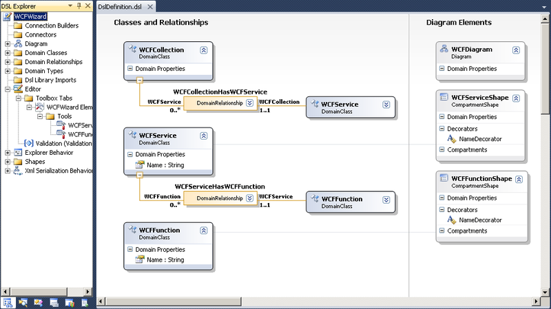
Now we need to associate our WCFService with a WCFCollection with a parent link, which will say that WCFService belongs to WCFCollection. For this, we extend Embedding Relationship from WCFCollection to WCFService. As a result, we got something similar to the picture.
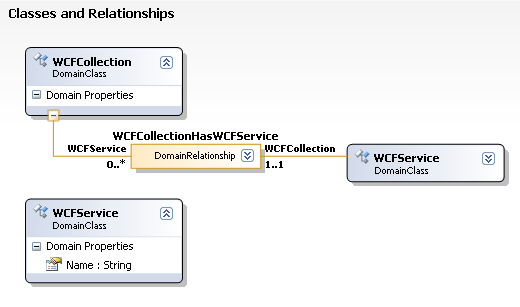
We have created a Domain Relationship object with the name "WCFCollectionHasWCFService". This object is responsible for the connection between the WCFCollection to the WCFService. All properties of this object are similar to those of the Domain Class , and the additional ones will be described separately.
| Property name | Description |
| Allows duplicates | If you set this property to True, then you will be allowed to create additional Embedding Relationships on the WCFService object. |
| Base Relationship | The basic link whose properties we want to inherit. |
| Is embedding | Indicates that the link is Embedding, or not. |
To the right of the Domain Relationship is “WCFService / 0 .. *” (has the type Domain Role ), where WCFService is the property name of the WCFCollection object, which contains references to the WCFService objects. 0 .. * is a connection type that says that in WCFCollection there may be a WCFService number from zero to infinity.
To the left of Domain Relationship is “WCFCollection / 1..1” (has the type of Domain Role ), where WCFCollection is the name of the property of the WCFService object, which contains a reference to the WCFCollection object. 1..1 - connection type, which says that in WCFService there should be exactly one (mandatory) reference to the WCFCollection object.
Domain Role describes the roles that exist in conjunction, as we can see from our example, each object (WCFService and WCFCollection) has its own role, which describes the behavior of communication on each side.
We describe the main distinctive properties of the Domain Role object.
| Property name | Description |
| Collection type | Allows you to specify the type of key to receive objects. In this case, we are not generating a list, but a collection. |
| Is Property Browsable | Specifies the visibility of the property for the user. |
| Is Property Generator | Determines whether a property is generated. |
| Property Custom Attributes | Allows attributes to be attached to a property. |
| Property Getter Access | Read access rights to the property. |
| Property Setter Access | The rights to access the property to write. |
| Multiplicity | Shows the number of objects created:
|
| Propagates Copy | The object that owns this role in the bundle will also be copied when the bundle is copied. |
| Propagates Delete | The object that owns this role in the bundle will also be deleted when the bundle is deleted. |
| Property Name | The name of the property to be generated. |
| Role player | The type of object to which the role belongs. |
Now we will save, click the “Transform All Templates” button, build the solution and start. Now we can add objects of type WCFService through WCFWizard Explorer in WCFCollection and give them names.
Creating a mapping on a chart
In order for our objects to start appearing in the diagram, we need to create a visual representation for them. For these purposes, use Toolbox elements: Geometry Shape , Compartment Shape , Connector . The first two render objects of type Domain Class , and the last is used for Domain Relationship .
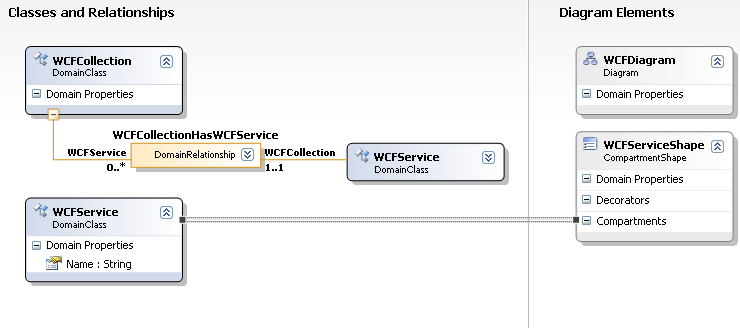
Add a Compartment Shape element and give it the name WCFServiceShape. This element has a number of properties responsible for its visual presentation, but it is also possible to produce a more flexible visual representation through the extension of the generated class.
To associate objects with their representation, you need to use the Diagram Element Map element and stretch the connection between WCFService and WCFServiceShape.
Let's see what we can add to our Compartment Shape :
- Compartment - displays a collection of properties.
- Domain Property is a property that will appear in Properties.
- Expand Collapse Decorator is an element that allows you to collapse and expand internal content.
- Icon Decorator - image display.
- Text Decorator - text output.
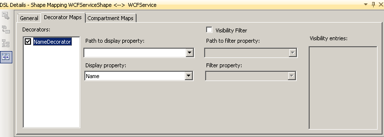
Add a Text Decorator and give it the name NameDecorator. Now you need to associate it with a specific property in WCFService; for this, use the DSL Details window. When selecting our Diagram Element Map , information about the bundle will appear. Go to the Decorator Maps tab and activate our NameDecorator. The Path to display property element can be left empty, since we will use the property directly WCFService, but with this element you can set the path to the associated object and then display its property. In the Display property element choose our name.
Now our WCFService has learned to display itself in the diagram.
Putting an object on the Toolbox
You can add objects through WCFWizard Explorer, but it does not look very nice. Let's try to add the ability to create an object through the Toolbox .
Let's go to DSL Explorer and in the Editor create a new Toolbox Tab, which we will give the name WCFWizard Elements. We created a group of elements for the Toolbox , in which we can create elements of two types: the Connection Tool (for connections) and the Element Tool (for objects).
Create an element of the Element Tool type, and give it the name WCFServiceTool, and take the icon from those that already exist in the resources. The most important thing is to set the Class property, which characterizes the object that should be created when dragging. Choose WCFService.
Now, on our Toolbox , the first object appeared that can be easily dragged onto the diagram.
Creating an object describing the "function"
We perform similar actions, as was done above for WCFService, only with the name WCFFunction. And we associate WCFFunction with WCFService (using Embedding Relationship ), and not with WCFCollection. And we get something next.
Now we can add functions to the service, but the diagram does not display them. Add a mapping to the bundle.
Drag the object of the Connector type (you can customize its external display in the properties) and associate it with the WCFServiceHasWCFFunction object using the Diagram Element Map .
Add an object that will describe the type of the object to set the parameters of the function and the return type.
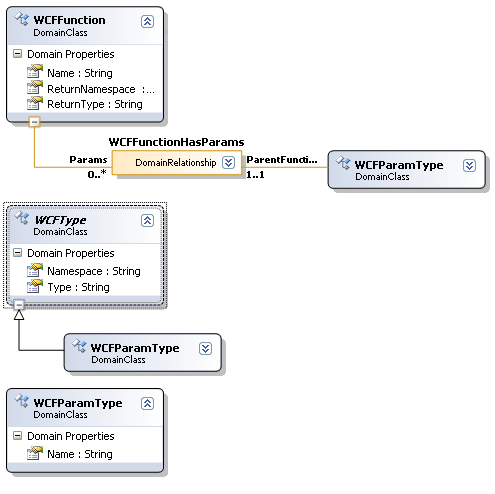
Add a Domain Class object with the name WCFType, and create two text properties in it: Namespace and Type, to set the namespace of the type and the type itself. Set the Inheritance Modifier property to the abstract state.
We also add a Domain Class object with the names WCFParamType (representing the function parameter set), which will be inherited from WCFType (setting the Base Class parameter to WCFType).
For WCFParamType, we will add another Name property to identify the name of the parameter in the function and associate it with the WCFService as shown in the figure.
Now in the WCFFunctionShape object we add a Compartment (let's call it Params). Let's go to the DSL Details panel with a dedicated link between WCFFunction and WCFFunctionShape. Select the Compartment Maps tab and customize as shown.
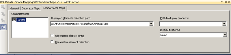
In the Displayed elements collection path field specify the path to the collection of elements that we go to display (using bundles), and then we specify the name of the property to be displayed.
Now we have enough information to start generating simple code.
This article does not include code generation, but I will say that you can go in different ways, I used two:
- Generate with T4.
- Generate directly from code, when saved.
Build and Deploy a Package
It is time to clarify the issue of installing our extension in Visual Studio . When building the project DSLPackage , we have a file with the extension vsix , which is the installation package.
To deploy our project, just run the vsix file and follow the steps of the installer.
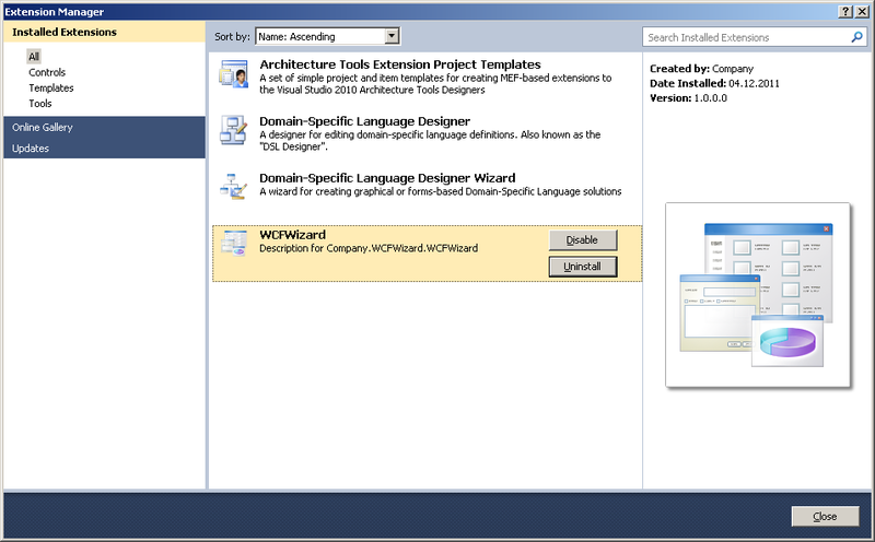
As a result, our extension will appear in Visual Studio and can be viewed in the Extension Manager (located in the Tools menu). Here you can also delete it.
Conclusion
I managed to illuminate only the smallest part of this tool, but I hope that this will encourage someone to do an independent in-depth study.
If this topic is of interest to people, then I have plans to highlight such issues as:
- Using menu items.
- Validation of data.
- Code generation
Source: https://habr.com/ru/post/134039/
All Articles