FTBB programmer for minimalist Arduino
Not so long ago, I told you how cheaply to build an Arduino-compatible board.
The only thing that was missing for a complete set was a programmer. Money for a full-fledged programmer is usually pitiful, especially if it is needed from time to time mainly for flashing a bootloader into a new chip.
Most programmer circuits do not solve the problems of chicken and eggs - the programmer also needs to be stitched with something. I also flashed my minimal Arduino with another Arduino board on hand. But not everyone has it, right? So you need a programmer that does not require firmware.
I did not reinvent the wheel and made a programmer based on a circuit published by DIHALT . In fact, they can flash any AVR microcontroller or use an USB-UART adapter. In general, it is useful.
Unfortunately, the DIHALT circuit contains logic and buffer chips, which were not at hand in the nearest store. Therefore, I decided to make the most simple option:
- Instead of switching modes on the buffer, logic and buttons, I decided to use just a jumper
- Replaced the USB-B connector on the USB Mini-B - such shoelaces are usually at hand, and the connector itself is significantly smaller.
-Have all the SMD trifle to the same size 0805 - resistors and capacitors in this size are cheaper, more affordable and do not have to look for different sizes for one board.
- Changed the assignment of pins so that they went in the same order as on the Arduino in the ISP programmer mode.
We will need:
1 FT232RL IC - from 132r
2 SMD capacitors per 100 nF - 2p each
1 mini-B USB connector - from 10p
1 piece of foiled PCB / getinaks 40x20 mm approximately.
1 sheet of photographic paper 120-180 g / m2 (which is on hand and crawls into the printer without getting stuck)
Optional :
1 PBS-6 socket
1 PBS-2 socket
3 SMD LEDs
3 SMD 510 ohm resistors
1 jumper 2.54 mm
')
We take photographic paper for an inkjet printer, the best is a glossy 120-180 g / m2. But I only had matte Lomond 180 g / m2 within availability.
We print the template on paper at maximum quality without saving toner at 100% scale.
Then we do everything as in the video tutorial at DI HALT
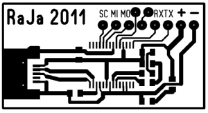
I did it the first time (except for the fact that at first I forgot to mirror the template). Here is the etched board:

" FTBB-PCB "
Tinned board with drilled holes (1mm drill, hand drill)
" FTBB-PCB "
Then, using the SMD soldering lesson, solder the FT232RL, USB connector, and a pair of capacitors.
In principle, at this moment you can connect to a computer and make sure that the device works and is detected in Windows.

" FTBB "
If you bought the optional components, then solder both sockets and resistors with LEDs on their backs on their places (if not, solder the wires directly to the pads)

" FTBB "
Do not pay attention to the posting, when I opened the jumper, I forgot the second hole in the diagram and therefore I had to solder the wire, what to do. In the attached file already corrected version.
Everything, then we do the cable with the standard for ArduinoISP contact scheme - Reset, MOSI, MISO, SCK (on the Arduino board these are pins D10, D11, D12, D13). VTG and GND are respectively connected to the "+" and "-" pins of the programmer.


" FTBB "
flashing a bootloader (bootloader) using avrdude modified to support FTBB.
I used FTBB for flashing the Atmega168P bootloader, soldered onto a breadboard.

" FTBB-Bootloading "
Is done. Now you can use the board as usual Arduino. Or you can flash your bootloader, or even just any suitable firmware without any bootloader.
With the jumper installed, we can flash the board so that it will work, you need to remove the jumper on the programmer or disconnect it from the board.
As a USB-UART adapter for flashing sketches, we will use our FTBB programmer by connecting the TX-RX pins to the corresponding Arduino pins. It will be stitched from the Arduino IDE as usual, you only need to click Reset on the board immediately after the sketch has been compiled. (I did not start a DTR pin, because I’m using another bootloader).
All necessary files :
AVRDudeR with atmega168p and booload.cmd settings for bootloader firmware (as well as a script for flashing an arbitrary .hex file and a connection test). I changed the pin assignment in the avrdude config to use the same cable as for the firmware using ArduinoISP.
Template for LUT + several variants of the board in Sprint Layout 5 format (2 variants of DI HALT and my two adaptations) and a sticker with pin signatures.
UPD corrected links to files LUT and firmware.
The only thing that was missing for a complete set was a programmer. Money for a full-fledged programmer is usually pitiful, especially if it is needed from time to time mainly for flashing a bootloader into a new chip.
Most programmer circuits do not solve the problems of chicken and eggs - the programmer also needs to be stitched with something. I also flashed my minimal Arduino with another Arduino board on hand. But not everyone has it, right? So you need a programmer that does not require firmware.
I did not reinvent the wheel and made a programmer based on a circuit published by DIHALT . In fact, they can flash any AVR microcontroller or use an USB-UART adapter. In general, it is useful.
Unfortunately, the DIHALT circuit contains logic and buffer chips, which were not at hand in the nearest store. Therefore, I decided to make the most simple option:
- Instead of switching modes on the buffer, logic and buttons, I decided to use just a jumper
- Replaced the USB-B connector on the USB Mini-B - such shoelaces are usually at hand, and the connector itself is significantly smaller.
-Have all the SMD trifle to the same size 0805 - resistors and capacitors in this size are cheaper, more affordable and do not have to look for different sizes for one board.
- Changed the assignment of pins so that they went in the same order as on the Arduino in the ISP programmer mode.
We will need:
1 FT232RL IC - from 132r
2 SMD capacitors per 100 nF - 2p each
1 mini-B USB connector - from 10p
1 piece of foiled PCB / getinaks 40x20 mm approximately.
1 sheet of photographic paper 120-180 g / m2 (which is on hand and crawls into the printer without getting stuck)
Optional :
1 PBS-6 socket
1 PBS-2 socket
3 SMD LEDs
3 SMD 510 ohm resistors
1 jumper 2.54 mm
')
We take photographic paper for an inkjet printer, the best is a glossy 120-180 g / m2. But I only had matte Lomond 180 g / m2 within availability.
We print the template on paper at maximum quality without saving toner at 100% scale.
Then we do everything as in the video tutorial at DI HALT
I did it the first time (except for the fact that at first I forgot to mirror the template). Here is the etched board:
" FTBB-PCB "
Tinned board with drilled holes (1mm drill, hand drill)
" FTBB-PCB "
Then, using the SMD soldering lesson, solder the FT232RL, USB connector, and a pair of capacitors.
In principle, at this moment you can connect to a computer and make sure that the device works and is detected in Windows.
" FTBB "
If you bought the optional components, then solder both sockets and resistors with LEDs on their backs on their places (if not, solder the wires directly to the pads)
" FTBB "
Do not pay attention to the posting, when I opened the jumper, I forgot the second hole in the diagram and therefore I had to solder the wire, what to do. In the attached file already corrected version.
Everything, then we do the cable with the standard for ArduinoISP contact scheme - Reset, MOSI, MISO, SCK (on the Arduino board these are pins D10, D11, D12, D13). VTG and GND are respectively connected to the "+" and "-" pins of the programmer.
" FTBB "
flashing a bootloader (bootloader) using avrdude modified to support FTBB.
:: writing Arduino bootloader
avrdude.exe -p m168p -c ftbb -P ft0 -U flash:w:ATmegaBOOT_168_diecimila.hex:a
:: writing fuses
avrdude.exe -p m168p -c ftbb -P ft0 -Uefuse:w:0x00:m -Uhfuse:w:0xdd:m -Ulfuse:w:0xff:m -Ulock:w:0x0F:m
I used FTBB for flashing the Atmega168P bootloader, soldered onto a breadboard.
" FTBB-Bootloading "
Is done. Now you can use the board as usual Arduino. Or you can flash your bootloader, or even just any suitable firmware without any bootloader.
With the jumper installed, we can flash the board so that it will work, you need to remove the jumper on the programmer or disconnect it from the board.
As a USB-UART adapter for flashing sketches, we will use our FTBB programmer by connecting the TX-RX pins to the corresponding Arduino pins. It will be stitched from the Arduino IDE as usual, you only need to click Reset on the board immediately after the sketch has been compiled. (I did not start a DTR pin, because I’m using another bootloader).
All necessary files :
AVRDudeR with atmega168p and booload.cmd settings for bootloader firmware (as well as a script for flashing an arbitrary .hex file and a connection test). I changed the pin assignment in the avrdude config to use the same cable as for the firmware using ArduinoISP.
Template for LUT + several variants of the board in Sprint Layout 5 format (2 variants of DI HALT and my two adaptations) and a sticker with pin signatures.
UPD corrected links to files LUT and firmware.
Source: https://habr.com/ru/post/133978/
All Articles