Continuation of the story about the "Heart" of an electronic device or the simplest programming Silicon Labs C8051F320
Not so long ago, I wrote an article about my craft on the basis of a Silicon Labs C8051F320 microcontroller. It's time to tell about the programming of this uk for simple tasks.
Details under the cut.
So, in the previous article I talked about a small scarf, which should be the basis of the future device. On it is located the microcontroller itself and its small kit designed for firmware reset, power supply, etc. One of the tasks that this device was supposed to perform at our place of work was to manage some of the devices on the research bench. Since, in essence, the task was not very difficult, the firmware for the mic did not require any complicated solutions like working with USB and other specific things, but the analysis of this firmware may in the future be good for those who will have to work with a similar mic on learning ( My friend seems to be programming the 51st kernel now or by work. But first things first.
')
The task was set fairly simple - to organize the simplest on / off of remote devices from the microcontroller, organizing the necessary delays between operations. In theory, it was necessary to still manage these delays from a PC via USB, but as it turned out later, this is not so important.
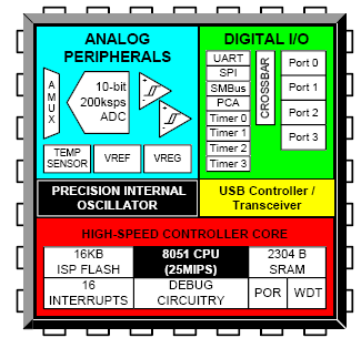
To solve this problem, it was necessary to implement the hardware part of the device, which is responsible for interfacing the remote control devices, since the “heart” itself did not carry anything on board, and it was originally intended to handle the peripheral board. I will not dwell on the hardware, as the article about the firmware, but still for the completeness of the picture I will present its scheme and a brief description.
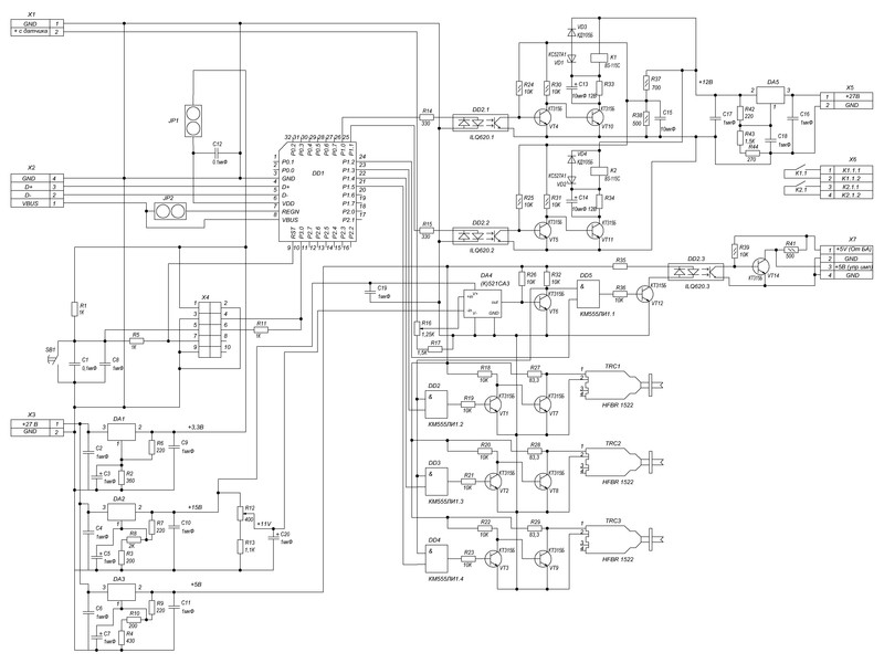
In total, there were 6 remote devices, three of which were controlled via fiber-optic communication, two through a relay and one with a simple pulse of 5 volts. Since our bosses do not like everything to be done wisely and, accordingly, they don’t want to allocate money for competent work, the concept was heaped up quickly and on the knee, so that there may be minor flaws. Here she is.
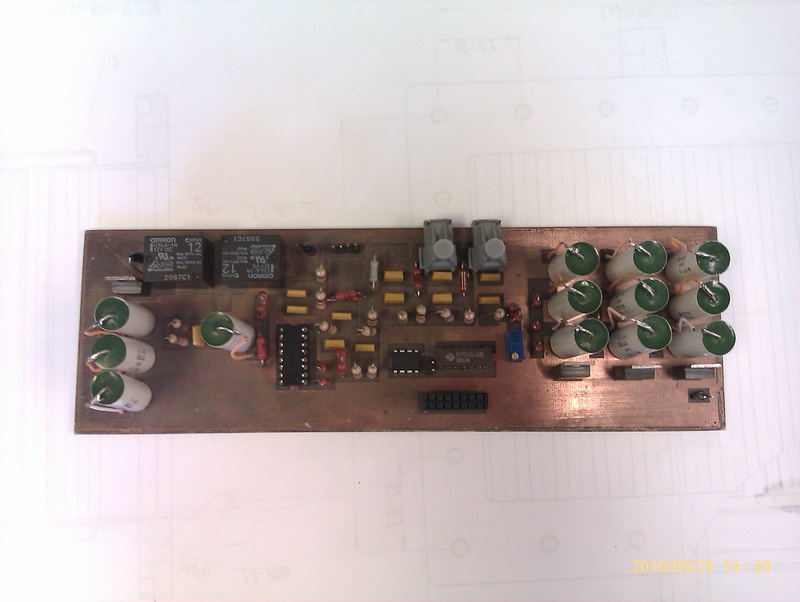
After making sure that no changes in the device are expected, or rather specifying with the authorities that there will not be any “Oh, let's get ...”, after which we will have to make a completely new scheme, we started to produce a printed circuit board. I have already said about the lack of money, so I would just say that everything was made from the improvised elements - the board was etched on our knee from a piece of old textolite, the elements were found in the storeroom. In general, complete devastation. Research institutes, what else to say ... In general, the result is visible in the photo:
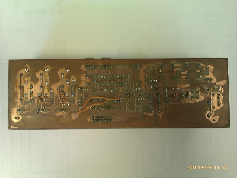
By the way, then everything happened “Oh, and let's ...”, so I had to rivet a couple of small handkerchiefs, cut the tracks on this one and put all the snot together, but the post is not about that.
The description of the program part will consist of several sub-paragraphs to make it easier to read and understand what it is all about.
The algorithm is simple as boots:
The algorithm is selected, the apatate part is ready, proceed to the configuration and programming of the microcontroller.
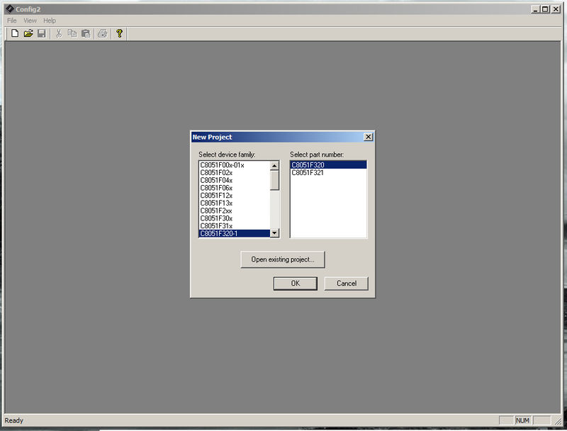
What I like about SILabs is that they have a bunch of buns in the form of programs for initializing, configuring, flashing and direct debugging of their microcontrollers. So, we take their program for the initial configuration of the IC from their site and launch it. Select in the settings we need MK and start the configuration.
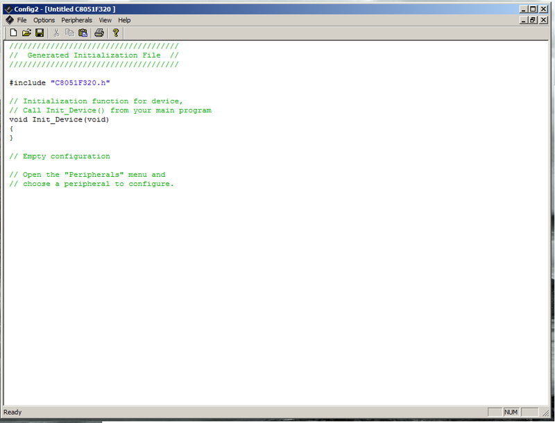
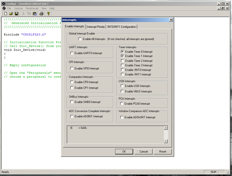
In the process of configuring the MK, we will need to configure its I / O ports so that they have a logical zero in the initial state, configure the timer-counter at the interval we need (EMNIP I set 50 microseconds), enable the timer interrupts and even small things. I do not remember exactly, I did it for a long time, I’ll just show you an example. In the Properties menu, select the item we need and see the open window, where all the parameters we need are configured in the GUI.
When you click OK, all settings are copied to the code window. Configured MK, but not in a hurry to close the configurator, it is still needed. We download from the same site Silicon Labs IDE , with which we will be flashing the MK. Run it.
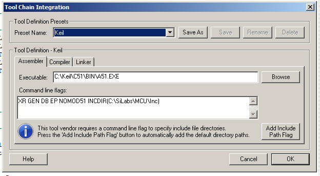
There is one nuance, she needs to slip the compiler from Keil C51 to use it. I will not dwell on it, just show the picture how to do it. Open the Project menu - Tool Chain Integration and specify the paths to the Keil compilers.
Open the configurator and copy the resulting code from it into the IDE.
So, the MC is configured, we proceed to the implementation of the main task - we check the incoming signal and work out the sequence.
The algorithm of this function is as follows: we start the timer for clicks every 50 microseconds. Create a global variable _state, which will be responsible for the current state of the controller. By default we make it equal to 0, i.e. the first state. The remaining states of the MC will be made more readable using define:
We look at the interrupt table on the controller datasheet and find out that the interrupt of the timer we need has a vector (number) 5. The code that implements the function:
So what are we doing? With each click of the timer, check the status of the MC. If it is 0, we check if there is a start signal at the input. If it is (inputPulse == 1) - run the sequence. The duration of the delays between signals is controlled by the number of timer clicks, checking it with each click in the state processing code. At the completion of the entire cycle of operation - we return the MC to the state 0 and wait for the next incoming signal.
MK is compiled and stitched up quite simply, from the same IDE by pressing one button. We connect the programmer to the board (as shown in the previous article), turn on the power, press the "Connect" button, then the "Download code" button. All MK flashed. You can run the code for execution in MK from here by pressing the “Go” button. Here you can set breakpoints and conduct a debug session with it, viewing the results on an oscilloscope.
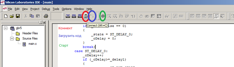
The buttons are shown in the picture and signed in different colors.
As you can see, not everything is so difficult when working with this MK. I think that this post will help someone to deal with it.
Details under the cut.
So, in the previous article I talked about a small scarf, which should be the basis of the future device. On it is located the microcontroller itself and its small kit designed for firmware reset, power supply, etc. One of the tasks that this device was supposed to perform at our place of work was to manage some of the devices on the research bench. Since, in essence, the task was not very difficult, the firmware for the mic did not require any complicated solutions like working with USB and other specific things, but the analysis of this firmware may in the future be good for those who will have to work with a similar mic on learning ( My friend seems to be programming the 51st kernel now or by work. But first things first.
')
Task
The task was set fairly simple - to organize the simplest on / off of remote devices from the microcontroller, organizing the necessary delays between operations. In theory, it was necessary to still manage these delays from a PC via USB, but as it turned out later, this is not so important.
Hardware
To solve this problem, it was necessary to implement the hardware part of the device, which is responsible for interfacing the remote control devices, since the “heart” itself did not carry anything on board, and it was originally intended to handle the peripheral board. I will not dwell on the hardware, as the article about the firmware, but still for the completeness of the picture I will present its scheme and a brief description.
In total, there were 6 remote devices, three of which were controlled via fiber-optic communication, two through a relay and one with a simple pulse of 5 volts. Since our bosses do not like everything to be done wisely and, accordingly, they don’t want to allocate money for competent work, the concept was heaped up quickly and on the knee, so that there may be minor flaws. Here she is.
After making sure that no changes in the device are expected, or rather specifying with the authorities that there will not be any “Oh, let's get ...”, after which we will have to make a completely new scheme, we started to produce a printed circuit board. I have already said about the lack of money, so I would just say that everything was made from the improvised elements - the board was etched on our knee from a piece of old textolite, the elements were found in the storeroom. In general, complete devastation. Research institutes, what else to say ... In general, the result is visible in the photo:
By the way, then everything happened “Oh, and let's ...”, so I had to rivet a couple of small handkerchiefs, cut the tracks on this one and put all the snot together, but the post is not about that.
Software part
The description of the program part will consist of several sub-paragraphs to make it easier to read and understand what it is all about.
Work algorithm
The algorithm is simple as boots:
- Check the presence of an external signal "Start" from the upstream device
- If the signal is received - we work the specified sequence, having spat on check of operation of devices. By the way, this method seemed to me to be not quite correct, so I did a single check, so that I didn’t bang, but I implemented it just by hardware, and not in the firmware.
- We return to the first point
The algorithm is selected, the apatate part is ready, proceed to the configuration and programming of the microcontroller.
Configuring the microcontroller
What I like about SILabs is that they have a bunch of buns in the form of programs for initializing, configuring, flashing and direct debugging of their microcontrollers. So, we take their program for the initial configuration of the IC from their site and launch it. Select in the settings we need MK and start the configuration.
In the process of configuring the MK, we will need to configure its I / O ports so that they have a logical zero in the initial state, configure the timer-counter at the interval we need (EMNIP I set 50 microseconds), enable the timer interrupts and even small things. I do not remember exactly, I did it for a long time, I’ll just show you an example. In the Properties menu, select the item we need and see the open window, where all the parameters we need are configured in the GUI.
When you click OK, all settings are copied to the code window. Configured MK, but not in a hurry to close the configurator, it is still needed. We download from the same site Silicon Labs IDE , with which we will be flashing the MK. Run it.
There is one nuance, she needs to slip the compiler from Keil C51 to use it. I will not dwell on it, just show the picture how to do it. Open the Project menu - Tool Chain Integration and specify the paths to the Keil compilers.
Open the configurator and copy the resulting code from it into the IDE.
//--------------------------------------------------------------------------------// // Initialization of timer // //--------------------------------------------------------------------------------// void timerInit(void) { TMOD = 0x10; TMR2CN = 0x24; TF2LEN = 1; TMR2RLL = 0xCF; TMR2RLH = 0xFF; TMR2L = 0xCF; TMR2H = 0xFF; T2SPLIT = 0; T2SOF = 0; ET2 = 1; TMR2 = 0xffff; // set to reload immediately ET2 = 1; // enable Timer2 interrupts TR2 = 1; // start Timer2 } //--------------------------------------------------------------------------------// // Initialization of ports I/O // //--------------------------------------------------------------------------------// void portIOInit(void) { P1MDOUT = 0x7F; XBR1 = 0x40; P0 = 0x00; P1 = 0x00; P2 = 0x00; } //------------------------------------------------------------------------------// // Interrupts init // //------------------------------------------------------------------------------// void interruptsInit(void) { IP = 0x20; IE = 0xA0; } //----------------------------------------------------------------------------- // SYSCLK_Init //----------------------------------------------------------------------------- // // This routine initializes the system clock to use the internal 24.5MHz / 8 // oscillator as its clock source. Also enables missing clock detector reset. // void SYSCLK_Init (void) { OSCICN = 0xC3; // configure internal oscillator for // its lowest frequency RSTSRC = 0x04; // enable missing clock detector } //------------------------------------------------------------------------------// // Device init // //------------------------------------------------------------------------------// void deviceInit(void) { // disable watchdog timer PCA0MD &= ~0x40; // WDTE = 0 (clear watchdog timer SYSCLK_Init(); timerInit(); portIOInit(); interruptsInit(); EA = 1; // enable global interrupts //------------------------------------------------------------------------------// // Main function // //------------------------------------------------------------------------------// void main(void) { _delay1 = 0; _delay2 = 19980; _widthImp = 20; _cDelay = 0; _state = ST_IDLE; deviceInit(); while(1) { }; } } Implementation of the main task
So, the MC is configured, we proceed to the implementation of the main task - we check the incoming signal and work out the sequence.
The algorithm of this function is as follows: we start the timer for clicks every 50 microseconds. Create a global variable _state, which will be responsible for the current state of the controller. By default we make it equal to 0, i.e. the first state. The remaining states of the MC will be made more readable using define:
#define ST_IDLE 0 #define ST_DELAY_0 1 #define ST_RNT_START 2 #define ST_DELAY_1 3 #define ST_RNT_STOP 4 We look at the interrupt table on the controller datasheet and find out that the interrupt of the timer we need has a vector (number) 5. The code that implements the function:
//------------------------------------------------------------------------------// // Timer ISR // //------------------------------------------------------------------------------// void timerISR (void) interrupt 5 { TF2H = 0; TF2L = 0; // Clear Timer2 interrupt flag switch(_state) { case ST_IDLE: if (_inputPulse == 0) { _state = ST_DELAY_0; _cDelay = 0; } break; case ST_DELAY_0: _cDelay++; if (_cDelay>=_delay1) { _state = ST_RNT_START; _rntStart = ON; _cDelay = 0; } break; case ST_RNT_START: _cDelay++; if (_cDelay >= _widthImp) { _state = ST_DELAY_1; _rntStart = OFF; _cDelay = 0; } break; case ST_DELAY_1: _cDelay++; if (_cDelay >= _delay2) { _state = ST_RNT_STOP; _rntStop = ON; _cDelay = 0; } break; case ST_RNT_STOP: _cDelay++; if (_cDelay >= _widthImp) { _state = ST_IDLE; _rntStop = OFF; _cDelay = 0; } break; default: _state = ST_IDLE; break; } So what are we doing? With each click of the timer, check the status of the MC. If it is 0, we check if there is a start signal at the input. If it is (inputPulse == 1) - run the sequence. The duration of the delays between signals is controlled by the number of timer clicks, checking it with each click in the state processing code. At the completion of the entire cycle of operation - we return the MC to the state 0 and wait for the next incoming signal.
Firmware
MK is compiled and stitched up quite simply, from the same IDE by pressing one button. We connect the programmer to the board (as shown in the previous article), turn on the power, press the "Connect" button, then the "Download code" button. All MK flashed. You can run the code for execution in MK from here by pressing the “Go” button. Here you can set breakpoints and conduct a debug session with it, viewing the results on an oscilloscope.
The buttons are shown in the picture and signed in different colors.
Conclusion
As you can see, not everything is so difficult when working with this MK. I think that this post will help someone to deal with it.
Source: https://habr.com/ru/post/133856/
All Articles