Using OpenGL Shaders in QML
This post participates in the competition "Smart phones for smart posts"
This post focuses on the use of OpenGL shaders along with elements of the declarative QML language. The theme, in my opinion, is relevant, as in the future version of QML 2.0 it is planned to use OpenGL extensively as a backend for drawing graphical interface elements. Writing shaders is not an easy topic, and the purpose of this post is that, first of all, a person, after reading it, can immediately try to do something interesting for himself and experiment, having received, for example, the following examples:

')
At the end, I will provide useful links where you can see the material for further, more in-depth study of this topic, if it will certainly interest you, and implement even more interesting shaders by applying them together with elements of the QML language. Work with shaders can be seen on the example of various QML elements: ShaderEffectItem , multiple Qt3D classes that also use OpenGL, etc. In this post I will demonstrate some examples using the
The following is an outline of this article as a whole:
Setting the ShaderEffectItem and ShaderEffectSource
Some shader theory
Linking QML elements with shaders
Example 1. Gradient implementation with shaders
Example 2.1 The simplest animation
Example 2.2 Creating a menu with animation
Example 3. Select some area of the texture depending on the mouse pointer.
Example 4. Mixing two images
Conclusion
useful links
Let's start with its installation of the necessary elements.
First you need to check whether you have installed all the components of OpenGL.
1) Follow the link and you will see the address in the git repository where the shadersplugin lies. If nothing has changed, then it is:
2) Making
3) Go to the folder and do make install (as I do under Linux, see how similar elements are installed under your OS). If there are no OpenGL components, then there will be installation problems. If you have any problems with this check, simply create an empty Qt application and add a line to the project file (* .pro):
Familiar with the concept of shaders can skip this small chapter. In it, I will give a brief overview of this topic. Why do we need shaders? In simple terms, shaders allow the programmer to “intervene” in the primitive rendering process, i.e. make changes to the stages of the pipeline (which will be discussed below), by writing the actual code. For writing shaders, there is a GLSL (OpenGL Shading Language) language created by the OpenGL committee. Its syntax is based on the programming language C. GLSL was designed specifically for programmers to have control over the programmed points of the OpenGL pipeline, which is a sequence of stages through which OpenGL commands pass). As one and variants of the conveyor shown in the figure below:
The vertex of any object is passed to the pipeline. First, the coordinate transformation (Vertex Transformation) is performed - the application of the world, species and projection matrices of the incoming vertex. This refers to the work of the vertex shader. After these operations are completed, the primitive layout (Assembly) occurs: at this stage, the spatial coordinates (x, y, z) are transformed using matrices of dimension (4 x 4). The main task is to obtain screen, two-dimensional coordinates from three-dimensional (world) coordinates. In this part of the pipeline, the vertices are grouped into triangles and fed into the rasterization (Rasterization). The rasterizer divides a triangle into fragments (pixels) for which texture coordinates and color are interpolated. Then comes the work of the fragment shader. He is responsible for determining the color of each pixel of the screen inside the area bounded by a contour projected onto the screen of the surface being drawn. After processing all these methods, the resulting fragment is placed in the frame buffer, which is subsequently displayed on the screen (Pixel updates).
As you already understood, shaders are of two types: vertex and fragment (or they are also called pixel). The vertex shader is executed earlier and processes each vertex, while the fragment shader is executed for each pixel to which some set of attributes are associated, such as color (
It is also worth mentioning some elements of the GLSL language, which will be found in the examples below:
It is also worth mentioning that GLSL defines a set of built-in functions focused on calculations, in particular for working with vectors and matrices. In the course of the analysis of the examples below, some functions will be discussed.
A mandatory requirement for the operation of shaders with QML elements is the installation of OpenGL for drawing, in an object of the QDeclarativeView class:
This piece of code is taken from the main function of the application,
As mentioned above, to demonstrate how to work with OpenGL shaders, the
It is allowed to define one or more
In QML, it is possible to define your properties for an element (using
If we consider the whole process as abstract as possible, then the graphic representation of the QML element is transferred by the texture to the vertex and fragment shaders, and then the final result is displayed, which will be displayed on the screen. Accordingly, it is possible to make changes in the rendering of this texture in shader programs (we are again returning to why shaders are needed at all).
Below we will consider a few examples and give some explanations to them. In order not to complicate the material in them, work will be shown everywhere using the example of writing fragment shaders, that is, we will work with pixels.
Let's start with a very simple example. In QML, there is a fairly frequently used Rectangle element and it has a
Now let's pay attention to the
The changing parameter
Since
on
Instead of the vector coordinates
Let's try to make some kind of animation using the shader mechanism.
We will do a little bit of a silly effect, but still ... As if the planet beats like a heart. First you need to use
The amplitude of oscillations is set using
Here is a video of the result of using such a fragment shader for the image of the planet:
Source code is available here.
It looks pretty nice and I decided to try the same effect for the menu buttons. So that when you hover on a button, there is an effect similar to the planet. This description presents an example of creating a menu in QML, from here in this manual. Each button is described in
File Button.qml:
Well, the menu.qml file itself
I want to draw attention to the fact that in the
Source code is available here.
Next, I want to give an example of changing the color of pixels in some part of the image. The area will be determined by the position of the mouse pointer, which will be the center of a circle with a radius of 50 pixels. And this circle will have colors of pixels different from the original.
First, in this example, you need to define 3 properties in the
They will determine, respectively, the coordinates of the mouse, passed into the shader code and the radius of the circle. The
You can see that the pow squaring function is used (it works similarly to the function with the same name in C / C ++ from the math library) to determine whether a point of a given pixel with a coordinate (
Accordingly, if the pixel coordinate falls into our circle, then the result is a pixel scalarly multiplied by a vector that defines gray color (the
The output of the following:
It is worth noting that here we apply conditional operators (exactly the same as in C), which are available in GLSL.
Source code is available here.
Suppose we have two pictures:
Coffee mug

and coffee beans:
We want to make a background in the form of coffee beans and a coffee mug on it. To solve this problem, we will again need to work with texture coordinates. In
The result vector
You can make a lot of experimental options with the parameters of the mix function and vector values (for example, the fourth element of the vector responsible for transparency, 1.0 and 0.4 in the example above) and get different, interestingly mixed textures.
Source code is available here.
In conclusion, I want to say that I think the examples given are fairly simple and trivial, but on the other hand, they can be useful to those who are not at all familiar with this topic and want to try to do something similar.
Summing up, we can say that thanks to the possibility of writing shader programs, we get very flexible mechanisms for working with the most important stages of processing OpenGL graphics when rendering QML elements. It is also worth noting that the GLSL language, as already mentioned, is very similar to C, but as stated in the official specification there are differences. For example, there are no pointers (data is passed to a function by value), recursion cannot be used in any way, etc. It should be remembered that a badly or incorrectly written shader program can have a dramatic effect on performance. The operation of these plug-ins has been tested on platforms: Symbian ^ 3, Maemo 5, Mac OS X, Windows 7 and Ubuntu. The platform requirements themselves are the Qt SDK version 4.7.x and QtOpenGL support.A future version of QML - QML2 in its Scene Graph will support the API combining GL / GLES shaders with QML code. You can consider the element in Qt 5.0ShaderEffect . If I correctly understood this and there is some semblance of what I wrote above.
This post focuses on the use of OpenGL shaders along with elements of the declarative QML language. The theme, in my opinion, is relevant, as in the future version of QML 2.0 it is planned to use OpenGL extensively as a backend for drawing graphical interface elements. Writing shaders is not an easy topic, and the purpose of this post is that, first of all, a person, after reading it, can immediately try to do something interesting for himself and experiment, having received, for example, the following examples:
')
At the end, I will provide useful links where you can see the material for further, more in-depth study of this topic, if it will certainly interest you, and implement even more interesting shaders by applying them together with elements of the QML language. Work with shaders can be seen on the example of various QML elements: ShaderEffectItem , multiple Qt3D classes that also use OpenGL, etc. In this post I will demonstrate some examples using the
ShaderEffectItem element together with the ShaderEffectSource .The following is an outline of this article as a whole:
Setting the ShaderEffectItem and ShaderEffectSource
Some shader theory
Linking QML elements with shaders
Example 1. Gradient implementation with shaders
Example 2.1 The simplest animation
Example 2.2 Creating a menu with animation
Example 3. Select some area of the texture depending on the mouse pointer.
Example 4. Mixing two images
Conclusion
useful links
Let's start with its installation of the necessary elements.
Install the necessary plugins
First you need to check whether you have installed all the components of OpenGL.
1) Follow the link and you will see the address in the git repository where the shadersplugin lies. If nothing has changed, then it is:
git://gitorious.org/qt-labs/qml1-shadersplugin.git2) Making
git clone git://gitorious.org/qt-labs/qml1-shadersplugin.git3) Go to the folder and do make install (as I do under Linux, see how similar elements are installed under your OS). If there are no OpenGL components, then there will be installation problems. If you have any problems with this check, simply create an empty Qt application and add a line to the project file (* .pro):
QT += declarative opengl . If everything compiles, there should be no problems during the installation.Some shader theory
Familiar with the concept of shaders can skip this small chapter. In it, I will give a brief overview of this topic. Why do we need shaders? In simple terms, shaders allow the programmer to “intervene” in the primitive rendering process, i.e. make changes to the stages of the pipeline (which will be discussed below), by writing the actual code. For writing shaders, there is a GLSL (OpenGL Shading Language) language created by the OpenGL committee. Its syntax is based on the programming language C. GLSL was designed specifically for programmers to have control over the programmed points of the OpenGL pipeline, which is a sequence of stages through which OpenGL commands pass). As one and variants of the conveyor shown in the figure below:
The vertex of any object is passed to the pipeline. First, the coordinate transformation (Vertex Transformation) is performed - the application of the world, species and projection matrices of the incoming vertex. This refers to the work of the vertex shader. After these operations are completed, the primitive layout (Assembly) occurs: at this stage, the spatial coordinates (x, y, z) are transformed using matrices of dimension (4 x 4). The main task is to obtain screen, two-dimensional coordinates from three-dimensional (world) coordinates. In this part of the pipeline, the vertices are grouped into triangles and fed into the rasterization (Rasterization). The rasterizer divides a triangle into fragments (pixels) for which texture coordinates and color are interpolated. Then comes the work of the fragment shader. He is responsible for determining the color of each pixel of the screen inside the area bounded by a contour projected onto the screen of the surface being drawn. After processing all these methods, the resulting fragment is placed in the frame buffer, which is subsequently displayed on the screen (Pixel updates).
As you already understood, shaders are of two types: vertex and fragment (or they are also called pixel). The vertex shader is executed earlier and processes each vertex, while the fragment shader is executed for each pixel to which some set of attributes are associated, such as color (
.r, .g, .b, .a ), depth, texture coordinates ( .x, .y, .z, .w or .s, .t, .p, .q ). The entry point to the shader is the void main() function. If the program uses both types of shaders, then there are two entry points main. Before entering the main function, global variables are initialized. Special types of variables are defined in GLSL:uniform - shader communication with external data (in the case of QML, these will be properties of elements (property)), it should be noted that this type of variables is read only;varying - this type of variables is necessary to connect a fragmentary shader with a vertex shader, that is, to transfer data from a vertex shader to a fragment shader. In the vertex shader, they can be changed, and in the fragment shader they are read-only;attribute - global scope variables;It is also worth mentioning some elements of the GLSL language, which will be found in the examples below:
sampler2D is one of the GLSL types representing texture (there is also sampler1D, sampler3D, samplerCube, sampler1Dshadow, sampler2Dshadow);vec4 texture2D(sampler2D s, vec2 coord) is a function used to read a pixel from texture s , with texture coordinates coord .gl_FrontColor is a vector in which final color texture data is written and which is available only in a fragment shader.It is also worth mentioning that GLSL defines a set of built-in functions focused on calculations, in particular for working with vectors and matrices. In the course of the analysis of the examples below, some functions will be discussed.
Linking QML elements with shaders
A mandatory requirement for the operation of shaders with QML elements is the installation of OpenGL for drawing, in an object of the QDeclarativeView class:
QmlApplicationViewer viewer; ... QGLWidget* glWidget = new QGLWidget(format); ... viewer.setViewport(glWidget); ... This piece of code is taken from the main function of the application,
main generated in QtCreator (Qt Quick Application Wizard), the QmlApplicationViewer class QmlApplicationViewer inherited from QDeclarativeView . After each example, I will provide a link to the full source code.As mentioned above, to demonstrate how to work with OpenGL shaders, the
ShaderEffectItem element will be used, which allows you to make changes to the display on the screen of various QML elements using OpenGL mechanisms. It is available in the Qt.labs.shaders 1.0 module (since it is under development), but now you can try using it. For writing vertex and fragment shader code, the properties (of type string ) fragmentShader and vertexShader are defined respectively.ShaderEffectSource required to specify the QML component to be available in the shader. It will mainly use the properties of sourceItem and hideSource . The first points to a specific QML element (its identifier) that will be affected by the shaders, and hideSource “says” that the original element will be hidden when the shaders effect is applied.It is allowed to define one or more
ShaderEffectItems as source (s) for other ShaderEffectItems , but you should not declare ShaderEffectItems as a child of an element defined in source , since this will most likely cause a redrawing loop.In QML, it is possible to define your properties for an element (using
property ), and they will also be available as variables in shader programs. This happens automatically if their names match and the variable in the shader is declared with the uniform qualifier already mentioned - the so-called binding. When we get to the examples, this moment will be immediately clear.If we consider the whole process as abstract as possible, then the graphic representation of the QML element is transferred by the texture to the vertex and fragment shaders, and then the final result is displayed, which will be displayed on the screen. Accordingly, it is possible to make changes in the rendering of this texture in shader programs (we are again returning to why shaders are needed at all).
Below we will consider a few examples and give some explanations to them. In order not to complicate the material in them, work will be shown everywhere using the example of writing fragment shaders, that is, we will work with pixels.
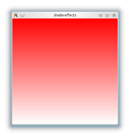
Example 1. Gradient implementation with shaders
Let's start with a very simple example. In QML, there is a fairly frequently used Rectangle element and it has a
gradient property. In the example below, I want to show how the gradient can be achieved using the shader mechanism. So, a Rectangle element with dimensions 360 by 360 will be created. It is also necessary to add a ShaderEffectItem element as a child to the Rectangle , with the anchors.fill property anchors.fill with a value of parent . Thus, we say that the shader "covers" the entire parent element. The code is presented below: import QtQuick 1.0 import Qt.labs.shaders 1.0 Rectangle { width: 360 height: 360 ShaderEffectItem { anchors.fill: parent fragmentShader: " varying highp vec2 qt_TexCoord0; void main(void) { lowp vec4 c0 = vec4( 1.0, 1.0, 1.0, 1.0 ); lowp vec4 c1 = vec4( 1.0, 0.0, 0.0, 1.0 ); gl_FragColor = mix( c0, c1, qt_TexCoord0.y ); } " } } Now let's pay attention to the
fragmentShader property - it contains the text of the fragment shader program. First, we define the variable varying highp vec2 qt_TexCoord0 , which we get from the vertex shader, although it is not defined by us, it has a default implementation and we can get data from there. qt_TexCoord0 determines, as I understand it, the texture coordinates of the scene as a whole (I will be glad if someone qt_TexCoord0 me and tells you what it is called correctly, in terms of computer graphics). Now let's turn to the main function. We define in it two vectors c0 containing white color (the color is represented as rgba) and c1 is red, and then we assign to the output vector gl_FragColor value obtained for each pixel using the mix function, a linear interpolation function between two values:mix (vec4 x, vec4 y, float a) - is expressed by the formula: x * ( 1.0 - a )+y * aThe changing parameter
a here will be the .y value of the texture vector corresponding to the vector coordinate along the y axis. Accordingly, the output will be as follows:Since
qt_TexCoord0.y represents the vector coordinate along the y axis, the gradient will be from top to bottom, if, for example, we want a gradient from left to right, we need to replace the line: gl_FragColor = mix( c0, c1, qt_TexCoord0.y ); on
gl_FragColor = mix( c0, c1, qt_TexCoord0.x ); .x means the vector coordinate of x . And if we want to just paint over everything in red, without any gradient, then there will be such a code (here absolutely all pixels are painted in red): void main(void) { gl_FragColor = vec4 ( 1.0, 0.0, 0.0, 1.0 ); } Instead of the vector coordinates
x and y , you can use texture s and t respectively. The result will be the same. Source code is available here.Let's try to make some kind of animation using the shader mechanism.
Example 2.1 The simplest animation
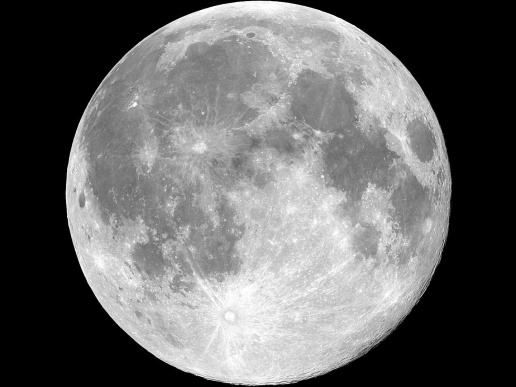
Let's apply shaders to work with the image of the planet:We will do a little bit of a silly effect, but still ... As if the planet beats like a heart. First you need to use
ShaderEffectSource to define a property in the Item element, for example, under the name source . In the same shader, we specify uniform lowp sampler2D source; thereby making the binding of our texture (the image of the planet) to the shader code and the ability to make changes to its rendering. To create any animation you need to change some data in time. For this, I will use the QML PropertyAnimation element. And what kind of data we need to change? Here I want to show an example of how to replace the data of one pixel with the data of another and thereby get the effect of animation. Those. for example, we have a pixel with x, y texture coordinates (as well as color data), and we substitute some neighboring pixel (with our own color data) instead, and we will choose it as some increment obtained for some functions, let it be a sin function. Therefore, as variable data, it is desirable to have an angle from 0 to 360 degrees. Thus, if you look at the code below in PropertyAnimation angle property is set to change from 0.0 to 360.0 . import QtQuick 1.0 import Qt.labs.shaders 1.0 Item { width: img.width height: img.height Image { id: img source: "images/space.jpg" } ShaderEffectItem { property variant source: ShaderEffectSource { sourceItem: img; hideSource: true } anchors.fill: img fragmentShader: " varying highp vec2 qt_TexCoord0; uniform lowp sampler2D source; uniform highp float angle; void main() { highp float wave = 0.01; highp float wave_x = qt_TexCoord0.x + wave * sin( radians( angle + qt_TexCoord0.x * 360.0 ) ); highp float wave_y = qt_TexCoord0.y + wave * sin( radians( angle + qt_TexCoord0.y * 360.0 ) ); highp vec4 texpixel = texture2D( source, vec2( wave_x, wave_y ) ); gl_FragColor = texpixel; }" property real angle : 0.0 PropertyAnimation on angle { to: 360.0 duration: 800 loops: Animation.Infinite } } } The amplitude of oscillations is set using
highp float wave = 0.01 . Why do I need the function of radians I think no need to explain. But if we substitute just the value of the angle angle picture will simply move different sides, and we also need something more spectacular - a “beating”. Texture coordinates vary from 0 to 1, respectively, for each pixel there will be a “multiplication in the sin function by an angle of 360”. In wave_x and wave_y I will record the coordinates of a pixel from some neighboring neighborhood, taken along the x axis and along the y axis y respectively. With texture2D( source, vec2( wave_x, wave_y ) ); we take the values of this new pixel and write them into the gl_FragColor we already know.Here is a video of the result of using such a fragment shader for the image of the planet:
Source code is available here.
Example 2.2 Creating a menu with animation
It looks pretty nice and I decided to try the same effect for the menu buttons. So that when you hover on a button, there is an effect similar to the planet. This description presents an example of creating a menu in QML, from here in this manual. Each button is described in
Button.qml . I added a bit to her description of work with shaders. The fragment shader code is almost the same as the example above, only I slightly increased the oscillation amplitude wave = 0.02 :File Button.qml:
import QtQuick 1.0 import Qt.labs.shaders 1.0 Item { width: but.width height: but.height property alias text: textItem.text Rectangle { id: but width: 130; height: 40 border.width: 1 radius: 5 smooth: true gradient: Gradient { GradientStop { position: 0.0; color: "darkGray" } GradientStop { position: 0.5; color: "black" } GradientStop { position: 1.0; color: "darkGray" } } Text { id: textItem anchors.centerIn: parent font.pointSize: 20 color: "white" } MouseArea { property bool ent: false id: moousearea anchors.fill: parent onEntered: { ent = true } onExited: { ent = false effect.angle = 0.0 } hoverEnabled: true } } ShaderEffectItem { id: effect property variant source: ShaderEffectSource { sourceItem: but; hideSource: true } anchors.fill: but property real angle : 0.0 PropertyAnimation on angle { id: prop1 to: 360.0 duration: 800 loops: Animation.Infinite running: moousearea.ent } fragmentShader: " varying highp vec2 qt_TexCoord0; uniform lowp sampler2D source; uniform highp float angle; void main() { highp float wave = 0.02; highp float wave_x = qt_TexCoord0.x + wave * sin( radians( angle + qt_TexCoord0.x * 360.0 ) ); highp float wave_y = qt_TexCoord0.y + wave * sin( radians( angle + qt_TexCoord0.y * 360.0 ) ); highp vec4 texpixel = texture2D( source, vec2( wave_x, wave_y ) ); gl_FragColor = texpixel; }" } } Well, the menu.qml file itself
import QtQuick 1.0 import Qt.labs.shaders 1.0 Item { width: 150 height: 190 Column { anchors.horizontalCenter: parent.horizontalCenter Button { text: "Apple" } Button { text: "Red" } Button { text: "Green" } Button { text: "Blue" } } } I want to draw attention to the fact that in the
onExited event, onExited necessary to reset the angle property of the effect element element to 0.0, otherwise the angle substituted into the calculation of the neighboring pixel will begin to be calculated not from 0, but from the last value, and not exactly what we expect. The result is this effect:Source code is available here.
Example 3. Select some area of the texture depending on the mouse pointer.
Next, I want to give an example of changing the color of pixels in some part of the image. The area will be determined by the position of the mouse pointer, which will be the center of a circle with a radius of 50 pixels. And this circle will have colors of pixels different from the original.
First, in this example, you need to define 3 properties in the
ShaderEffectItem element:property real xPos: 65.0property real yPos: 65.0property real radius: 50They will determine, respectively, the coordinates of the mouse, passed into the shader code and the radius of the circle. The
MouseArea element and handling of the onPositionChanged event are defined to track the mouse movement. Below is the source code and further explanation: Rectangle { width: img.width height: img.height Image { id: img source: "images/nature.jpg" } ShaderEffectItem { id: effect anchors.fill: parent MouseArea { id: coords anchors.fill: parent onPositionChanged: { effect.xPos = mouse.x effect.yPos = coords.height - mouse.y } } property real xPos: 65.0 property real yPos: 65.0 property real radius: 50 property int widthImage: img.width property int heightImage: img.height property variant source: ShaderEffectSource { sourceItem: img; hideSource: true } fragmentShader: "varying highp vec2 qt_TexCoord0; uniform highp float xPos; uniform highp float yPos; uniform highp float radius; uniform highp int widthImage; uniform highp int heightImage; highp vec2 pixcoords = qt_TexCoord0.st * vec2( widthImage, heightImage ); uniform sampler2D source; void main(void) { lowp vec4 texColor = texture2D(source, qt_TexCoord0.st); lowp float gray = dot( texColor, vec4( 0.6, 0.5, 0.1, 0.0 ) ); if ( ( pow( ( xPos - pixcoords.x ), 2 ) + pow( ( yPos - pixcoords.y ), 2 ) ) < pow( radius, 2 ) ) { gl_FragColor = vec4( gray, gray, gray, texColor.a) ; } else { gl_FragColor = texture2D( source, qt_TexCoord0 ); } }" } } You can see that the pow squaring function is used (it works similarly to the function with the same name in C / C ++ from the math library) to determine whether a point of a given pixel with a coordinate (
pixcoords.x; pixcoords.y ) pixcoords.x; pixcoords.y into a circle with center at xPos and yPos and radius .Accordingly, if the pixel coordinate falls into our circle, then the result is a pixel scalarly multiplied by a vector that defines gray color (the
dot function performs the scalar product). If not, then the specific pixel does not change. Again, you can see how the intermittent QML of an element is associated with shader program variables — they have the same name and equivalent types: real equivalent to highp float .The output of the following:
It is worth noting that here we apply conditional operators (exactly the same as in C), which are available in GLSL.
Source code is available here.
Example 4. Mixing two images (textures)
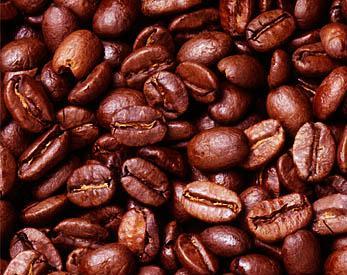
Suppose we have two pictures:
Coffee mug
and coffee beans:
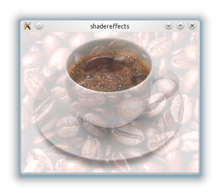
We want to make a background in the form of coffee beans and a coffee mug on it. To solve this problem, we will again need to work with texture coordinates. In
ShaderEffectItem two images texture0 and ShaderEffectItem will be defined as elements of ShaderEffectSource . In the fragment shader code, these two images will be stored as two textures in a uniform sampler2D texture0 and a uniform sampler2D texture1 .In the variables s1and s2we get the texture coordinates of each pixel of the first image and the second, respectively, as shown in the code below: import QtQuick 1.0 import Qt.labs.shaders 1.0 Rectangle { width: coffee.width height: coffee.height Image { id: coffee source: "images/coffee.jpg" } Image { id: granules source: "images/granules.jpg" } ShaderEffectItem { anchors.fill: parent id: effect property variant texture0: ShaderEffectSource { sourceItem: coffee; hideSource: true } property variant texture1: ShaderEffectSource { sourceItem: granules; hideSource: true } fragmentShader: " varying highp vec2 qt_TexCoord0; uniform sampler2D texture0; uniform sampler2D texture1; void main(void) { vec4 s1 = texture2D( texture0, qt_TexCoord0.st ); vec4 s2 = texture2D( texture1, qt_TexCoord0.st ) ; gl_FragColor = mix( vec4( s1.r, s1.g, s1.b, 1.0 ), vec4( s2.r * 0.6, s2.g * 0.6, s2.b * 0.6, 0.4 ), 0.35 ); }" } } The result vector
gl_FrontColorwill be recorded already familiar to us (during the creation of the gradient) the result of linear interpolation of two vectors containing the pixel color parameters. Moreover, each channel of color in the texture s2 (coffee beans will be multiplied by 0.6, since we need it as a background). As a result, we have the following result:You can make a lot of experimental options with the parameters of the mix function and vector values (for example, the fourth element of the vector responsible for transparency, 1.0 and 0.4 in the example above) and get different, interestingly mixed textures.
Source code is available here.
In conclusion, I want to say that I think the examples given are fairly simple and trivial, but on the other hand, they can be useful to those who are not at all familiar with this topic and want to try to do something similar.
Conclusion
Summing up, we can say that thanks to the possibility of writing shader programs, we get very flexible mechanisms for working with the most important stages of processing OpenGL graphics when rendering QML elements. It is also worth noting that the GLSL language, as already mentioned, is very similar to C, but as stated in the official specification there are differences. For example, there are no pointers (data is passed to a function by value), recursion cannot be used in any way, etc. It should be remembered that a badly or incorrectly written shader program can have a dramatic effect on performance. The operation of these plug-ins has been tested on platforms: Symbian ^ 3, Maemo 5, Mac OS X, Windows 7 and Ubuntu. The platform requirements themselves are the Qt SDK version 4.7.x and QtOpenGL support.A future version of QML - QML2 in its Scene Graph will support the API combining GL / GLES shaders with QML code. You can consider the element in Qt 5.0ShaderEffect . If I correctly understood this and there is some semblance of what I wrote above.
useful links
- I recommend to get acquainted with the official specification of OpenGL ES .
- QML ShaderEffectItem on QGraphicsView - here you can see examples of videos, shaders work on Nokia N8.
- GLSL guide , the theory of shaders work is described very well (sometimes the site lies with them, so don't be scared :))
- 6 interesting shader implementations
- Qt Quick 2 QML Scene Graph GLSL fragment shader tutorial
Source: https://habr.com/ru/post/133828/
All Articles