FPGA programming. Smoothly changing the brightness of the LEDs on the Spartan-3E Starter Kit using PWM
 This article is aimed at newcomers to programming FPGAs in the VHDL language and those who want to learn how to do it. Earlier in Habré, an article with a similar task implemented on a PIC controller was already reviewed. And in this article we will focus on changing the brightness of the LED with FPGA.
So, the purpose of the work: To master the concept of PWM and apply it in changing the brightness of the LED. To implement, use the VHDL programming language in the Xilinx ISE development environment Project Navigator v12.3 .
Let's go to the goal
To implement, we need some piece of hardware with FPGAs, I chose the Spartan-3E Starter Kit ( DataSheet ) that was on hand. You also need to install Xilinx ISE Project Navigator (I have installed version 12.3). In principle, everything is ready to work. It remains only to connect the power to the scarf and connect it via USB to a computer for further programming.
Part 1. Theory of changing the brightness of the LED.
The brightness of the LED can be adjusted by applying to it different values of DC voltage (for example, a variable resistor). But on our board there are LEDs without variable resistors, which can take the value '1' and glow at full brightness, or '0'. So how then to make the brightness adjustment for such a simple device? The answer is PWM. The whole point is that we will “blink” this LED so quickly that the blinking will not even be noticeable to our eyes, and we will just see a dimly lit LED. To put it more precisely, the LED just has a transition process during ignition, that is, it does not light up instantaneously. This is what we use, giving the unit for a very short period of time, so that the LED does not have time to light up at full brightness.
')
Part 2. Creating a new project.
Download the ISE Project Navigator and poke File -> New Project. We write the name of the project (I have shim_habr), select the directory to save and select the Top-level source type: HDL from below. Click Next.

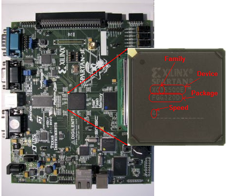
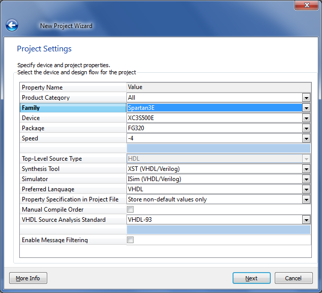
Next, select the FPGA. In my case, Family: Spartan3E; Device: XC3S500E; Package: FG320; Speed: -4. All these data can be seen on the microchip itself, or look in the datasheet.
Next, select Preferred Language: VHDL, click Next and then Finish.
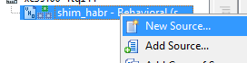
Project created. Now you need to add a module to it, in which we will describe the logic of the LED. At the top left we find the New Source button and click on it:

In the window that appears, select the VHDL Module and write any file name (you can do the same with the project shim_habr). Click Next.

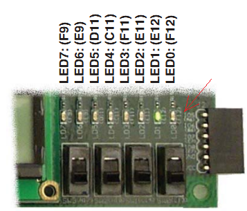
Now we need to specify the legs used in the project. You can not do this now and skip this step, and then write everything by hand. But since for our project we need only three legs, I introduced them right here. So, we need a reference frequency from the quartz installed on the 50 MHz board connected to the FPGA to the pin named C9, and we will also use two LEDs that are also installed on the board. Suppose it will be two right LEDs connected to the FPGA legs under the names E12 and F12. Let's call the clk quartz leg, set Direction: IN since we will read the frequency, and the legs with LEDs will use led1 and led2 with Direction: OUT, since we will manage them.
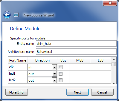
Click Next, then Finish. We see the opened text editor with the I / O ports of the project already completed.
entity shim_habr is
Port ( clk : in STD_LOGIC ;
led1 : out STD_LOGIC ;
led2 : out STD_LOGIC ) ;
end shim_habr ;
As I said, you could skip the previous step and enter it all manually. Next we need to match the names of the ports with the names of the FPGA legs. Right-click on the file name shim_habr.vhd in the hierarchy and select the item New Source.
In the window that opens, select Implementation Constrains File and call this file pin. Click Next, then Finish.

In the opened empty file we write the following:
NET "clk" LOC = "C9" ;
NET "led1" LOC = "F12" ;
NET "led2" LOC = "E12" ;
We save.
The numbers of the legs can be viewed in the datasheet, or in our case, we have simplified the search - the numbers can be viewed directly on the board next to the desired periphery:
Part 3. Programming constant brightness LED.
Switch to the file shim_habr.vhd and write the code:
architecture Behavioral of shim_habr is
constant clk_freq : integer : = 50 _000_000 ; - quartz frequency
constant shim_freq : integer : = 10 _000 ; - PWM frequency
constant max_count : integer : = clk_freq / shim_freq ; - bit width PWM
signal count : integer range 0 to max_count : = 0 ; - counter frequency divider
constant porog : integer : = max_count / 48 ; - pulse width of a logical unit
begin
process ( clk )
begin
if rising_edge ( clk ) then
if count = max_count then
count <= 0 ;
else
count <= count + 1 ;
end if ;
end if ;
end process ;
led1 <= ' 1 ' when count < porog else ' 0 ' ;
led2 <= ' 1 ' ;
end behavioral ;
Now let's see what this code does. First, note the line led2 <= '1'. We light the second LED at full brightness by feeding a logical unit there so that we can compare with the brightness of the first LED. Next, we look at the declared registers and constants. The constant clk_freq stores the frequency of quartz in hertz; shim_freq is the PWM frequency in hertz. Accordingly, in order to get the PWM period we need, it is necessary to divide the clock frequency by the PWM frequency, and we will get the number of clock cycles of the main quartz corresponding to the PWM period. In essence, this will be the PWM digit. The result of the division is written in the max_count constant. Next, create a count counter, which will cycle from 0 to max_count at 50 MHz. Create a process (clk). The condition if rising_edge (clk) then waits for the next “tick” from the quartz, and if it happens, it adds the count to the counter, checking whether it has reached the maximum value. Further, outside the process we write the line
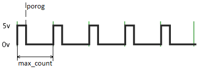
led1 <= ' 1 ' when count < porog else ' 0 ' ;
That is, a logical unit hangs on the LED when our counter is less than a certain porog threshold value (I have 1/48 of the entire period, see the declaration of constants), the rest of the period a logical zero hangs on the LED. This can be clearly shown by the picture:
Part 4. Firmware.
We save all changes, select the file shim_habr.vhd in the hierarchy and look for the Configure Target Device process from the bottom of the hierarchy and run it. We are waiting for the project to be translated into the firmware file, after which the iMPACT program window will open, with which we will be stitching it into the FPGA.
Double click on Boundary Scan, and if you have a board connected to your computer via USB, you will see something like this:
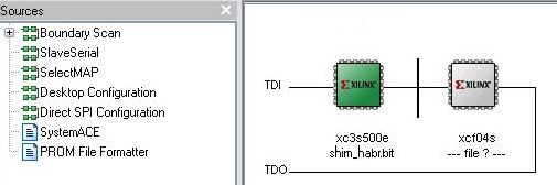
If you are not offered to choose the firmware file for xc3s500e, then right-click on the corresponding microcircuit and select the Assign Configuration File menu item. In the file selection window, select the newly created shim_habr.bit. Then again, right-click on xc3s500e, then Program. The flashing process starts, after which the words Program Successful will appear. If everything went that way, then you can look at the scarf =)
Part 5. Programming a smooth change in the brightness of the LED.
So, we see that two LEDs are on - one is bright, the other is dim. Now try to make a smooth change in brightness. To do this, we need to make porog not a constant, but a variable, and change it smoothly from minimum to maximum.
signal porog : integer range 0 to max_count : = 0 ;
In order to set the rate of change of the threshold, we need to divide the clock frequency again and get a smaller one. For example, we want the threshold to increase by 1 every 1/600 of a second. Create a counter:
constant max_count_div : integer : = clk_freq / 600 ;
signal count_div : integer range 0 to max_count_div : = 0 ;
and append to process (clk) at the moment of the next “tick” if rising_edge (clk) then another condition:
if count_div = max_count_div then
count_div <= 0 ;
- here the frequency is divided by 600.
else
count_div <= count_div + 1 ;
end if ;
Now we need to enter in the place where the frequency is divided by 600, increase the threshold by 1 and reset to 0 if the value reached the maximum:
if porog = max_count then
porog <= 0 ;
else
porog <= porog + 1 ;
end if ;
As a result, the overall picture will look like this:
architecture Behavioral of shim_habr is
constant clk_freq : integer : = 50 _000_000 ; - quartz frequency
constant shim_freq : integer : = 10 _000 ; - PWM frequency
constant max_count : integer : = clk_freq / shim_freq ; - bit width PWM
signal count : integer range 0 to max_count : = 0 ; - counter frequency divider
signal porog : integer range 0 to max_count : = 0 ; - pulse width of a logical unit
constant max_count_div : integer : = clk_freq / 600 ;
signal count_div : integer range 0 to max_count_div : = 0 ;
begin
process ( clk )
begin
if rising_edge ( clk ) then
if count = max_count then
count <= 0 ;
else
count <= count + 1 ;
end if ;
if count_div = max_count_div then
count_div <= 0 ;
if porog = max_count then
porog <= 0 ;
else
porog <= porog + 1 ;
end if ;
else
count_div <= count_div + 1 ;
end if ;
end if ;
end process ;
led1 <= ' 1 ' when count < porog else ' 0 ' ;
led2 <= ' 1 ' ;
end behavioral ;
We broadcast, sew, enjoy success. =) It may seem to you that the LED lights up most of the time, and it is dim only at the beginning of the cycle. I already wrote about this effect in my previous article about color music . The fact is that brightness depends on a threshold not linearly, but logarithmically. That is, for example, in order for the brightness to change smoothly from a minimum to a maximum using a PWM digit width of 1024, it is necessary to take successively the following values of the variable porog: 0, 16, 32, 64, 128, 256, 512, 1024.
Homework.
As you can see, the LED gradually picks up the brightness, and as soon as it is dialed, it immediately resets to 0 (in fact, they wrote it and got it). As a workout, you can try to make a smooth set of brightness, and when the maximum is reached, begin to smoothly reduce it to zero. Those who can easily cope with this task can try to make “running lights” out of eight available LEDs: the first diode lights up and goes off smoothly, then the second, and so on. If it does not work, but it is interesting, then ask - I will try to answer and explain.
Conclusion
So, we have mastered the use of PWM to the LED and learned how to adjust the brightness of the LED using FPGA. The same method can be used to regulate the rotational speed of the engine, the magnetic force of the coils, etc.
I wish you all success in the development of FPGA!
PS: I apologize, I forgot the source of the project for this article at work ... I’ll post it as soon as I take it from there (at home nothing is installed). But he is not much needed here, everything can be (and preferably it is necessary!) To do it yourself, from scratch.
UPD: Promised sources .
Source: https://habr.com/ru/post/133383/
All Articles