Automatic backlight for TV
On Habré, they like to watch TV , a monitor , a laptop and even a phone with a backlight.
The variant proposed below differs from those already considered in that the backlight turns on automatically, does not require a change in the design of the TV, and can work as an emergency lighting.
Among the shortcomings it should be noted that the backlight is static, it takes time to install and configure for specific equipment.
So, we need a backlight, which turns on when the room is dark enough and the TV is on, it burns in full, when the TV does not work, but the room is very dark and someone walks along it. In all other cases, the backlight should be turned off. Restrictions : equipment on a guarantee - it is impossible to climb inside.
')
To determine the mode of operation of the TV, we will be using this thing here:

TAK12-02 High-frequency Pulse Current Transformer
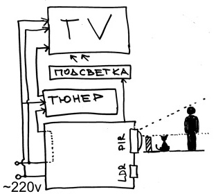
The device allows, by pushing one of the power wires into the hole, to remove the induced current from the contacts, and by its magnitude to make a conclusion about the mode of operation of the TV. Suppose that for a TV in sleep mode, the current consumption will be significantly lower than in the active one. Illumination will be measured by the photoresistor aka LDR, fixing around the room with the help of PIR , arduinka will control everything. The scheme turned out this:

Backlight wiring diagram
The backlight is an LED strip pasted on a plastic corner. While he just lies behind the TV, then screw it to the wall.
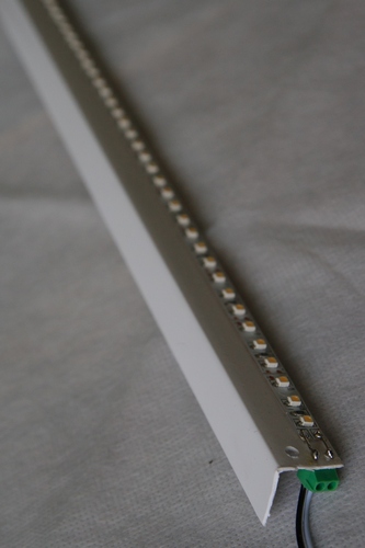
Backlight

Ready device
After the first test launches, I was waiting forepic fail a little disappointment - it turned out that the plasma TV was falling asleep very hard - it might take him up to half an hour (see the chart below). In addition, he is very anxious asleep, waking up every 2-3 hours for 15-20 minutes.

Panasonic TX-P50G30 goes to sleep. The Y axis is the current in parrots, the X axis is the time in seconds x2.
All this, plus the cat on which the PIR worked, led to the fact that in the living room all the night light worked. But given that the TV is only used in conjunction with a tuner, and he has less sleep problems, the problem was solved, though not as beautiful as planned. It was possible to reduce the influence of kote on the system by sealing the bottom of the PIR.
Refined backlight wiring diagram
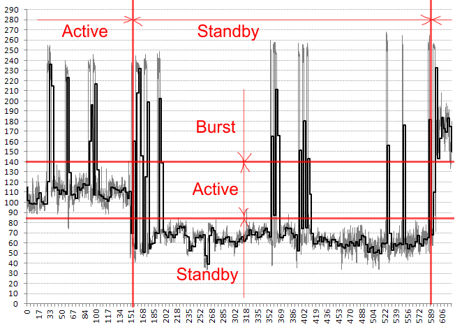
Current consumption tuner. The Y axis is the current in parrots, the X axis is the time in minutes.
As can be seen in the picture above, the tuner, unlike the TV, immediately goes into sleep mode, which is noticeable by the decrease in current. The tuner also has moments of extreme power consumption, marked on the “burst” chart, at which they can occur both in sleep and active modes. In order to increase the reliability of determining the mode of operation, the flow of measurements was divided into series of 3 minutes, for each series was considered the mean value (SOC) and the standard deviation (SD). We took into account only the values of the series with a small SKO and NW not falling into the “burst” zone. All of this allowed, with a delay, but rather accurately determining the mode of operation of the tuner.
Expenses:
In circuit design, I am not strong, the details were taken on the principle of "what is", I will be grateful for comments and additions:
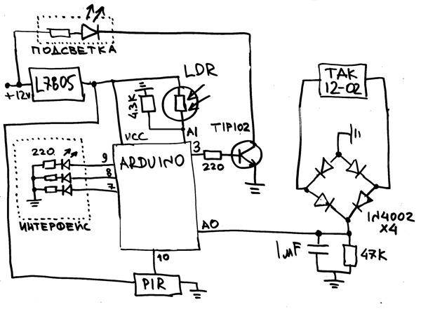
Electrical circuit, not the principal.
Arduino sketch can be found here .
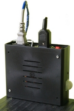
Device assembly.

Backlight in the work.
Update.
now suggested replacing TAK12-02 with an ACS712 chip. The devices are similar in price but the ACS712 works more precisely.
Since the idea of controlling the current consumption is not an ideal way to determine the mode of the TV, I conclude with co- author ploop , biggestfruit , Obramko , RaJa , mmib , Ocelot , eldarmusin , Arezus , MisterX , Tamahome and other respected commentators on the following table.
Update 2.
Practice has shown that the Hall effect ACS712 microcircuit measures the current much more accurately than the TAK12-02 transformer. Therefore, its use is preferable.

The signal from the ACS712 when measuring current consumption by a computer. 0 corresponds to a voltage of 2.5V
The variant proposed below differs from those already considered in that the backlight turns on automatically, does not require a change in the design of the TV, and can work as an emergency lighting.
Among the shortcomings it should be noted that the backlight is static, it takes time to install and configure for specific equipment.
Formulation of the problem
So, we need a backlight, which turns on when the room is dark enough and the TV is on, it burns in full, when the TV does not work, but the room is very dark and someone walks along it. In all other cases, the backlight should be turned off. Restrictions : equipment on a guarantee - it is impossible to climb inside.
')
Decision
To determine the mode of operation of the TV, we will be using this thing here:
TAK12-02 High-frequency Pulse Current Transformer
The device allows, by pushing one of the power wires into the hole, to remove the induced current from the contacts, and by its magnitude to make a conclusion about the mode of operation of the TV. Suppose that for a TV in sleep mode, the current consumption will be significantly lower than in the active one. Illumination will be measured by the photoresistor aka LDR, fixing around the room with the help of PIR , arduinka will control everything. The scheme turned out this:
Backlight wiring diagram
Implementation
The backlight is an LED strip pasted on a plastic corner. While he just lies behind the TV, then screw it to the wall.
Backlight
Ready device
After the first test launches, I was waiting for
Panasonic TX-P50G30 goes to sleep. The Y axis is the current in parrots, the X axis is the time in seconds x2.
All this, plus the cat on which the PIR worked, led to the fact that in the living room all the night light worked. But given that the TV is only used in conjunction with a tuner, and he has less sleep problems, the problem was solved, though not as beautiful as planned. It was possible to reduce the influence of kote on the system by sealing the bottom of the PIR.
Refined backlight wiring diagram
Current consumption tuner. The Y axis is the current in parrots, the X axis is the time in minutes.
As can be seen in the picture above, the tuner, unlike the TV, immediately goes into sleep mode, which is noticeable by the decrease in current. The tuner also has moments of extreme power consumption, marked on the “burst” chart, at which they can occur both in sleep and active modes. In order to increase the reliability of determining the mode of operation, the flow of measurements was divided into series of 3 minutes, for each series was considered the mean value (SOC) and the standard deviation (SD). We took into account only the values of the series with a small SKO and NW not falling into the “burst” zone. All of this allowed, with a delay, but rather accurately determining the mode of operation of the tuner.
Expenses:
| TAK12-02 | $ 5 |
| 1m led strip | $ 11 |
| Harduinka | $ 10 |
| Power Supply | $ 8 |
| PIR | $ 6 |
| Cables, connectors, housing, prototyping board, Circuits, wires, svetodidy, etc. | $ 15 |
| Total | $ 55 |
In circuit design, I am not strong, the details were taken on the principle of "what is", I will be grateful for comments and additions:
Electrical circuit, not the principal.
Arduino sketch can be found here .
findings
- The idea to determine the mode of operation of the device for power consumption, in practice, was not so good. The cumbersome algorithm, a significant lag in the work, the need for fine-tuning, make the commercial implementation of the Idea impossible, but as a project hobby it has the right to life.
- Energy statistics collected during the work gives reason to think about what household appliances do with sleep mode, especially if it is connected to the Internet.
Device assembly.
Backlight in the work.
Update.
- The sharp-sighted ploop noticed a mistake in the electrical circuit, thanks, corrected.
- Took into account the fair remark of Ocelot and slightly changed the name of the topic.
- Added a picture of the TV with working lights, just as an illustration of the fact that by throwing the LED tape behind the TV you can exalt the comfort of viewing. I will not do the video - in my opinion for static lighting it is not informative.
- Transferred to DIY, thanks for the karma.
now suggested replacing TAK12-02 with an ACS712 chip. The devices are similar in price but the ACS712 works more precisely.
Since the idea of controlling the current consumption is not an ideal way to determine the mode of the TV, I conclude with co- author ploop , biggestfruit , Obramko , RaJa , mmib , Ocelot , eldarmusin , Arezus , MisterX , Tamahome and other respected commentators on the following table.
Alternatives
| Way | Virtues | disadvantages |
|---|---|---|
| Submerge to status LED | reliably | |
| Put the OP to control the status LED | reliably | changing the front panel of the TV - not aesthetically pleasing |
| Catching pickups with a sweep of a plasma TV using an antenna placed behind the screen | research is needed, only suitable for plasma | |
| Control the temperature of the TV | simplicity, reliability | delay in detection, additional wires from the sensor, perhaps only suitable for plasma |
| Analyze the presence of a signal on one of the wires included in the SCART connector | simplicity, reliability | research is needed, one of the connectors will be busy, additional wires |
| Put the OP in front of the TV and determine the screen glow | If you put a matrix from the OP, you can organize a full ambient light | additional wires, placement complexity, need for an additional optical system |
| Catch the IR signal on the on-off TV | simplicity, minimum wires | no feedback - malfunctions are possible |
| Monitor the availability of power on the USB port | simplicity, reliability | not suitable for all TVs, takes a USB port, additional wires |
| Analyze the current consumed by the TV | minimum of wires | complex algorithm, the delay in determining not applicable to all TVs |
Update 2.
Practice has shown that the Hall effect ACS712 microcircuit measures the current much more accurately than the TAK12-02 transformer. Therefore, its use is preferable.
The signal from the ACS712 when measuring current consumption by a computer. 0 corresponds to a voltage of 2.5V
Source: https://habr.com/ru/post/132852/
All Articles