About unnecessary Spanning Tree

Immediately make a reservation, do not take the title too literally. If the stars are lit ... and so on.
Nevertheless, the Spannning Tree protocol family, if it does not outlive its age as the main backup tool in ethernet networks, then at least smoothly flows into narrow and specific niches (of course, their discussion goes beyond any framework of this article, but is welcomed in comments).
')
And yes, of course, no one has canceled Spanning Tree as a technology to protect against human error.
Why is it needed
First, allow yourself a couple of platitudes. Of course, they can be learned from Wikipedia, but we can not resist.
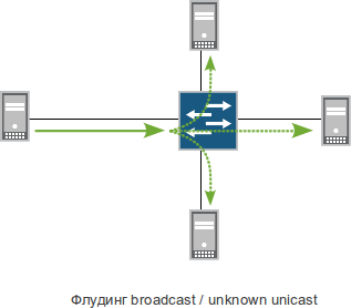
Since the BOC model (also known as ISO / OSI, if you like it more) forgot to endow the channel layer with the functions of selecting the optimal transmission path and excluding hooks, which put it on the network layer, Ethernet does not have such functions. Instead of a hassle with a preliminary calculation of the path to the destination address, the ethernet switch, if it does not know where to send the frame, sends it to all ports, except the port through which the transmitted frame was received. And there, you see, there is an addressee capable of comprehending by content that this is a frame for him. (When we talk about flooding to all ports, except in very special cases, we are talking only about the ports of one VLAN.)
The switch would not be a switch, if it were limited to this. Still, he is not so stupid, and in order not to send everything to everyone at all times, he looks at the source addresses and writes them to himself in a label: the MAC address of such and such is located behind such and such port. The process is called learning MAC addresses (“macroning”). Having formed such a table (switching table), the switch sends frames only to the necessary ports.
If, on top of Ethernet, IP traffic is transmitted, and most often it is, then frames with unknown destination MAC addresses should not occur in a good scenario (and direct hands), but there is no way to do without special frames with a destination address “Send to all”, the transfer of which boils down to the same.
Total, in ethernet-networks flooding, that is, copying the frame to all possible output ports is an integral part of the switching process.
Now imagine what happens if a loopback is found in the network topology. One of the copies of the frame will return to the switch that failed it, which will again elucidate it, and so on until all the devices on the network have a processor load of one hundred percent. The situation described is called a Broadcast storm. Who ever observed - will not lie, the spectacle is not for the faint of heart.

If you and your neighbor agreed to forget about home lokalku, buying a pair of plastic switches in the store, do not try for greater speed and greater reliability to connect them with two wires instead of one: it will not be better, that's at least.
On the one hand - what is easier? - Do not stick extra wires, and that's all. But not so easy. After all, I want the network to be fault-tolerant, with redundant connections, redundant nodes and automatic failover. In other words, so that the L2 network was like L3. To achieve the desired and, at the same time, to protect themselves from the horror of broadcasted storms, people came up with special technologies to search for cycles in the topology and force them to break by blocking individual links. These technologies are called the word Spanning Tree.
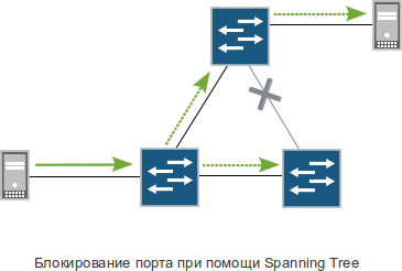
It is technology, in the plural. After all, it’s not enough to say “block”, it is still important to understand which link to block, after what period of time to check, whether it’s time to unblock, how to do it, which ports you can not check for hooking, which VLANs should be sent via which links, how quickly it all happens, etc. Different views on these and many other issues have created a whole heap of protocols with the common name Spanning Tree: STP, RSTP, PVST, PVST +, PVRST, MSTP, VSTP, and there must be more.
Readers, who have seriously studied any of the above, are probably familiar with the sensation, similar to the combination of drowsiness and toothache, which occurs in the process of studying all these endless port states, weights forming mechanisms, root switch selection algorithms, and other skukoteni, which is inferior to boring except anatomy textbook. Those who have successfully coped with the introduction, operation, troubleshooting and network development of at least a dozen switches, built on the basis of a spanning tree, can safely serve
Spanning Tree in English means "branching tree." And a tree is, in turn, a “connected acyclic graph,” that is, a graph without cycles (hooks), between which two vertices there exists at least one path.
Why it is not necessary
Now, finally, about why Spanning Tree is rapidly losing its relevance.
You, of course, have already heard that in the bright future, everything will be, firstly, common, secondly virtual,
Linking technology into aggregated LAG aka EtherChannel groups did not appear yesterday.
By the way, the linking in LAG and the LACP protocol should not be confused in itself, which helps to make this union (semi) automatically, but because of the inept handling in life, it has more problems than good.
The idea is simple. Two switches — however, not necessarily switches, any devices operating at the second and higher levels — are connected for reliability by two wires, not just one. At the same time, the switches are configured (manually or by means of LACP) in such a way that for them the two wires are one link. We will not go into details too much, there are plenty of articles for every taste, we just say that aggregation can be done in one of two ways: “active – active” (most popular): traffic is transmitted over two wires at once with load balancing; and “active – passive”: while one link is in “an”, the second is in “down”, when the main one drops, it switches to the backup one.
In essence, the above is the easiest way to get rid of Spanning Tree on the “one-generation” level. However, this method generally requires that both links on each side be connected to the same switch. Otherwise, the same hooks or complications associated with the constant updating of the table of MAC addresses are possible.
But here comes a relatively (relatively) modern invention to the aid - switch clustering. With its help, several physical devices can be combined into one logical one. Traditionally, this function is considered to be “beautiful”, designed primarily to simplify management. However, the main advantages of clustering switches are quite different. In addition to some technical and commercial aspects , clustering is also a reduction in the number of nodes in the topology while maintaining redundancy of physical devices.

Today, the main driver of the growing popularity of clustered switches is precisely the possibility of combining ports on different physical devices in a cluster into LAG. Thus, we are able to connect one access switch (in which user links are stuck) to two switch aggregations without any spanning tree. Similarly, if there are more levels, the aggregators can be connected via a LAG group to the core (if you have one) or backbone.

Word about scale
Initially, clustering appeared on 24/48 × 1GE (+ 2 × 10GE) format switches, that is, devices of relatively small scale. Depending on the manufacturer and model, such switches can be clustered in a cluster either using special interfaces (PCI Express, InfiniBand, etc.), which are limited in length to a few meters, or via regular ports 1 or 10 Gigabit Ethernet, incl. optical. In the latter cases, it is possible to build geographically distributed switches and even small metro-ethernet networks . Depending on the specific implementation and model, it is usually possible to combine from two to ten devices into one cluster.
After some time, manufacturers began to implement clustering on large modular switches. They typically use several 10 Gigabit Ethernet interfaces for intra-cluster links. The maximum number of such devices per cluster is usually substantially less (2–4), however, there is no particular crime in this.
In addition to modular switches, clustering is also found on the full hardware routers of the older lines of individual manufacturers. From a theoretical point of view, this function is less relevant for routers due to the presence of native routing mechanisms, load balancing, and traffic engineering in IP / MPLS networks. But since such devices are often used to perform L2 functions (PE for L2VPN / VPLS services or combining L3 and L2 in one box), clustering support on them is also important and is used primarily for the same: combining different LAG interfaces physical devices to back up second level connections.
And yet the bright future will not be free. In some aspects, a switch cluster is worse than many individual switches. For example, the table of MAC addresses on all devices is usually one. Accordingly, the top bar of the maximum number of entries in it applies to the entire cluster. For a network of 10 devices of a small city scale, a limit of 10–15 thousand MAC addresses may be a significant limitation; Some implementations, for example, require the simultaneous reboot of all cluster devices when updating software. This kind of nuances depending on the specific model of devices can be quite a lot. All this makes clustering a questionable approach to building carrier networks.
Total
The combination of clustering switches and aggregating the interfaces of different devices into LAG groups is the most efficient way to build fault-tolerant L2 networks of enterprises, campuses (several buildings of a single administrative office located next to each other), data centers, and individual providers' network nodes. For most of the parameters: switching speed, stability, reliability, ease of setup operation and troubleshooting, load balancing - this approach greatly exceeds the variations on the Spanning Tree theme.
However, this technology is not a panacea, you should not take it as a mechanism for building real L2-carrier-scale networks.
In addition, Spanning Tree, although losing its relevance as a mechanism for building a fault-tolerant topology and balancing, but, as already mentioned, remains an important way to protect against human error. Therefore, if, for example, RSTP or PVST + is enabled by default on the switch, you should not turn it off unless you are sure that you know exactly why. It is also desirable that one switch be used on all switches, but this is a completely different story.
Source: https://habr.com/ru/post/132312/
All Articles