Linear algebra for game developers
This article is a translation of a cycle of four articles “Linear algebra for game developers”, written by David Rosen and dedicated to linear algebra and its application in game development. The original articles can be found here: part 1 , part 2 , part 3 and part 4 . I did not publish translations in separate topics, but combined all the articles into one. I think that it will be more convenient to perceive the material and work with it. So let's get started.
One of the directions in linear algebra is the study of vectors. If your game uses positioning of on-screen buttons, working with the camera and its direction, the speed of objects, then you will have to deal with vectors. The better you understand linear algebra, the more control you get over the behavior of vectors and, therefore, over your game.
In games, vectors are used to store locations, directions, and speeds. Below is an example of a two-dimensional vector:
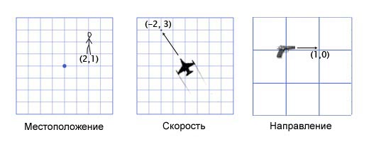
The location vector (also called the "radius vector") indicates that a person is two meters east and one meter north of the starting point. The speed vector shows that for a unit of time the plane moves three kilometers up and two miles to the left. The direction vector tells us that the gun is pointing right.
')
As you can see, the vector itself is just a set of numbers that takes on a particular meaning depending on the context. For example, a vector (1, 0) can be both a direction for a weapon, as shown in the picture, and coordinates of a building one mile east of your current position. Or the speed of the cochlea, which moves to the right at a speed of 1 mile per hour ( approx. Translator: rather quickly for a snail, 44 centimeters per second ).
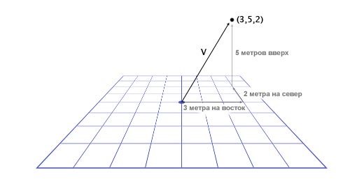
It is important to track units. Suppose we have a vector V (3,5,2). This tells us little. Three what, five what? In our game, Overgrowth distances are indicated in meters and speeds in meters per second. The first number in this vector is the direction to the east, the second is the direction up, the third is the direction to the north. Negative numbers denote opposite directions, west, down, and south. The location defined by the vector V (3,5,2) is located three meters to the east, five meters above and two meters north, as shown in the image below.
So, we learned the basics of working with vectors. Now we learn how to use vectors.
To add vectors, we just need to add each of their components to each other. For example:
(0, 1, 4) + (3, -2, 5) = (0 + 3, 1-2, 4 + 5) = (3, -1, 9)
Why do we need to add vectors? Most often vector addition in games is used for physical integration. Any physical object will have vectors for location, speed, and acceleration. For each frame (usually one sixtieth of a second), we must integrate two vectors: add speed to location and acceleration to speed.
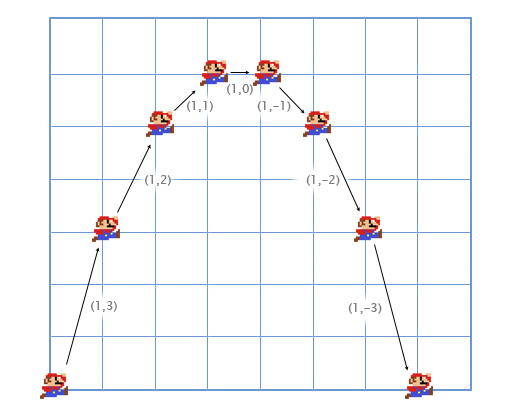
Let's look at the Mario jumping example. He starts from position (0, 0). At the moment of the start of the jump, his speed (1, 3), he quickly moves up and to the right. Its acceleration is (0, -1), as gravity pulls it down. The picture shows what his jump looks like, divided into seven frames. The black text shows its speed in each frame.
Let's take a look at the first frames in more detail in order to understand how everything happens.
For the first frame, we add Mario's speed (1, 3) to his location (0, 0) and get his new coordinates (1, 3). Then we add the acceleration (0, -1) with its speed (1, 3) and get the new value of the Mario speed (1, 2).
Do the same for the second frame. Add the speed (1, 2) to the location (1, 3) and get the coordinates (2, 5). Then we add acceleration (0, -1) to its speed (1, 2) and we get a new speed (1, 1).
Usually, the player controls the acceleration of the game character using the keyboard or gamepad, and the game, in turn, calculates new values for speeds and position using physical addition (through vector addition). This is the same problem that is solved in integral calculus , we just greatly simplify it for our game. I noticed that it was much easier for me to listen attentively to lectures on integral calculus, thinking about its practical application, which we have just described.
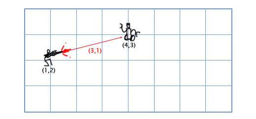
Subtraction is calculated according to the same principle as addition - we subtract the corresponding components of the vectors. Subtracting vectors is convenient for getting a vector that shows from one location to another. For example, let the player be located at the coordinates (1, 2) with a laser gun, and the enemy robot is located at the coordinates (4, 3). To determine the motion vector of the laser beam that will hit the robot, we need to subtract the player’s location from the robot’s location. We get:
(4, 3) - (1, 2) = (4-1, 3-2) = (3, 1).
When we talk about vectors, we call individual numbers scalars. For example (3, 4) is a vector, and 5 is a scalar. In games, it is often necessary to multiply a vector by a number (scalar). For example, simulating a simple air resistance by multiplying the player's speed by 0.9 in each frame. To do this, we need to multiply each component of the vector by a scalar. If the player’s speed is (10, 20), then the new speed will be:
0.9 * (10, 20) = (0.9 * 10, 0.9 * 20) = (9, 18).
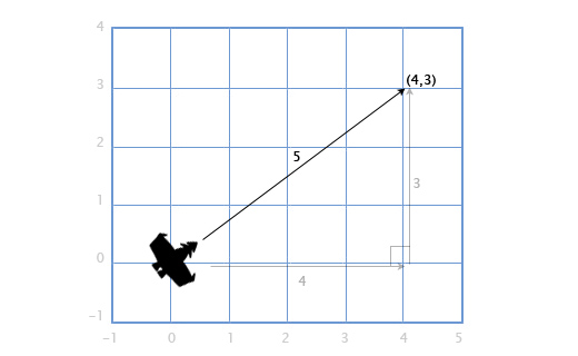
If we have a ship with a velocity vector V (4, 3), we will also need to find out how fast it is moving in order to calculate the need for screen space or how much fuel is needed. To do this, we need to find the length (modulus) of the vector V. The length of the vector is indicated by vertical lines, in our case the length of the vector V will be denoted as | V |.
We can represent V as a right triangle with sides 4 and 3 and, using the Pythagorean theorem, obtain the hypotenuse from the expression: x 2 + y 2 = h 2
In our case, the length of the vector H with the components (x, y) we get from the square root: sqrt (x 2 + y 2 ).
So, the speed of our ship is equal to:
| V | = sqrt (4 2 + 3 2 ) = sqrt (25) = 5
This approach is also used for three-dimensional vectors. The length of the vector with the components (x, y, z) is calculated as sqrt (x 2 + y 2 + z 2 )
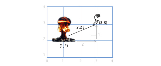
If player P is at point (3, 3), and the explosion occurred at point E by coordinates (1, 2), we need to determine the distance between the player and the explosion in order to calculate the degree of damage caused to the player. This is easy to do by combining the two operations described above: subtracting vectors and their length.
We subtract P - E to get a vector between them. And then we determine the length of this vector, which gives us the desired distance. The order of the operands does not matter here, | E - P | will give the same result.
Distance = | P - E | = | (3, 3) - (1, 2) | = | (2, 1) | = sqrt (2 2 +1 2 ) = sqrt (5) = 2.23
When we deal with directions (as opposed to locations and speeds), it is important that the direction vector has a length of one. This greatly simplifies our lives. For example, let's say the gun is turned in the direction (1, 0) and fires a projectile at a speed of 20 meters per second. What is the velocity vector for the projectile in this case?
Since the direction vector has a length equal to one, we multiply the direction by the velocity of the projectile and get the velocity vector (20, 0). If the same direction vector has a length other than one, we will not be able to do this. The projectile will be either too fast or too slow.
A vector with a length equal to one is called “normalized”. How to make a vector normalized? Pretty simple. We divide each component of the vector by its length. If, for example, we want to normalize a vector V with components (3, 4), we simply divide each component by its length, that is, by 5, and we get (3/5, 4/5). Now, using the Pythagorean theorem, we make sure that its length is equal to one:
(3/5) 2 + (4/5) 2 = 9/25 + 16/25 = 25/25 = 1
What is a scalar product (written as •)? To calculate the scalar product of two vectors, we must multiply their components, and then add the results together
(a1, a2) • (b1, b2) = a1b1 + a2b2
For example: (3, 2) • (1, 4) = 3 * 1 + 2 * 4 = 11. At first glance it seems useless, but let's take a closer look at this:
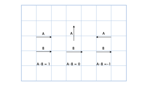
Here we can see that if the vectors are pointing in one direction, then their scalar product is greater than zero. When they are perpendicular to each other, the scalar product is zero. And when they point in opposite directions, their scalar product is less than zero.
Basically, using the scalar product of vectors, you can calculate how many of them are pointing in one direction. And although this is only a small part of the capabilities of the scalar product, it is already very useful for us.
Suppose we have a guard, located in G (1, 3) looking in the direction of D (1,1), with a viewing angle of 180 degrees. The main character of the game is watching him from the position H (3, 2). How to determine whether the protagonist is in sight of the guard or not? We do this by the scalar product of vectors G and V (a vector directed from the guard to the main character). We will get the following:
V = H - G = (3, 2) - (1, 3) = (3-1, 2-3) = (2, -1)
D • V = (1, 1) • (2, -1) = 1 * 2 + 1 * -1 = 2-1 = 1
Since the unit is greater than zero, the main character is in the field of view of the guard.

We already know that the scalar product is related to determining the direction of vectors. And what is its more precise definition? The mathematical expression of the scalar product of vectors is as follows:
A • B = | A || B | cosΘ
Where Θ (pronounced "theta") is the angle between vectors A and B.
This allows us to find Θ (angle) using the expression:
Θ = acos ([AB] / [| A || B |])
As I said earlier, normalizing vectors simplifies our lives. And if A and B are normalized, the expression is simplified as follows:
Θ = acos (AB)
Let's look again at the scenario with the guard. Let now the angle of view of the guard will be equal to 120 degrees. We obtain the normalized vectors for the direction of the guard's look (D ') and for the direction from the guard to the protagonist (V'). Then we define the angle between them. If the angle is more than 60 degrees (half of the viewing angle), then the main character is out of sight of the guard.
D '= D / | D | = (1, 1) / sqrt (1 2 + 1 2 ) = (1, 1) / sqrt (2) = (0.71, 0.71)
V '= V / | V | = (2, -1) / sqrt (2 2 + (-1) 2 ) = (2, -1) / sqrt (5) = (0.89, -0.45)
Θ = acos (D'V ') = acos (0.71 * 0.89 + 0.71 * (- 0.45)) = acos (0.31) = 72
The angle between the center of the field of view of the guard and the location of the main character is 72 degrees, hence the guard does not see him.

I understand that it looks quite difficult, but this is because we do everything manually. The program is all pretty simple. Below is shown how I did it in our Overgrowth game with the help of C ++ libraries I wrote for working with vectors:
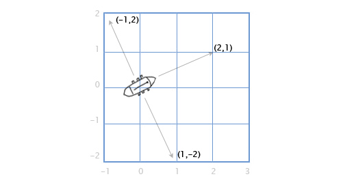
Suppose we have a ship with guns that shoot right and left along the course. Assume that the boat is located along the direction vector (2, 1). In what directions are guns firing now?
It is quite simple in 2D graphics. To rotate the direction 90 degrees clockwise, simply swap the components of the vector, and then swap the sign of the second component.
(a, b) turns into (b, -a). Consequently, for a ship located along the vector (2, 1), the cannons on the right along the board will fire in the direction (1, -2), and the guns from the left side will fire in the opposite direction. Change the signs of the components of the vector and get (-1, 2).
And what if we want to calculate this all for three-dimensional graphics? Consider the ship example.
We have the vector of the mast M directed straight up (0, 1, 0) and the wind direction: north-northeast W (1, 0, 2). And we want to calculate the direction vector of the sail S in order to “catch the wind” in the best way.
To solve this problem, we use the vector product: S = M x W.

The vector product A (a 1 , a 2 , a 3 ) and B (b 1 , b 2 , b 3 ) will be equal to:
(a 2 b 3 -a 3 b 2 , a 3 b 1 -a 1 b 3 , a 1 b 2 -a 2 b 1 )
Now we substitute the values we need:
S = MxW = (0, 1, 0) x (1, 0, 2) = ([1 * 2 - 0 * 0], [0 * 1 - 0 * 2], [0 * 0 - 1 * 1] ) = (2, 0, -1)
For manual calculations it is quite difficult, but for graphics and gaming applications, I recommend writing a function similar to the one below and not going into details of such calculations.
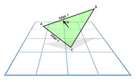
Vector artwork is often used in games to calculate surface normals. Directions in which this or that surface "looks". For example, consider a triangle with vectors A, B, and C. How do we find the direction in which the triangle "looks", that is, the direction perpendicular to its plane? It seems difficult, but we have a tool for solving this problem.
Use subtraction to determine the direction from A to C (C - A), let it be “face 1” (Edge 1) and the direction from A to B (B - A), let it be “face 2” (Edge 2) . And then we apply the vector product to find a vector perpendicular to both of them, that is, perpendicular to the plane of the triangle, also called the "normal to the plane."
This is what the code looks like:
In games, the basic expression of illuminance is written as N • L, where N is the normal to the illuminated surface, and L is the normalized vector of the direction of light. As a result, the surface looks bright when light directly falls on it, and dark when it does not occur.
We now turn to the consideration of such an important concept for game developers as the "transformation matrix" (transformation matrix).
To begin, examine the "building blocks" of the transformation matrix.
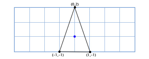
Suppose we write the game Asteroids on a very old "hardware" and we need a simple two-dimensional spacecraft that can freely rotate in its plane. The ship model looks like this:
How do we draw a ship when the player turns it to an arbitrary degree, say 49 degrees counterclockwise. Using trigonometry, we can write a two-dimensional rotation function that takes the coordinates of a point and the angle of rotation, and returns the coordinates of the offset point:
Applying this function to all three points, we get the following picture:

Operations with sines and cosines work rather slowly, but since we only make calculations for three points, it will work fine even on the old “hardware” ( note of the translator: in cases when it is intended to use trigonometric functions intensively, to speed up the calculations, Memory organizes tables of values for each function and calculates them when the application is started. Then, when calculating a particular trigonometric function, the table is simply referenced .
Let now our ship looks like this:
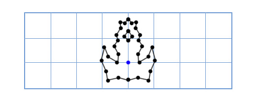
Now the old approach will be too slow, since it will be necessary to turn a fairly large number of points. One of the elegant solutions to this problem will sound like this: “What if, instead of turning each point of the ship model, we turn the coordinate grid of our model?”
How it works? Let's take a closer look at what the coordinates are.
When we talk about a point with coordinates (3, 2), we say that its location is three steps from the point of reference on the coordinate axis X, and two steps from the point of reference on the coordinate axis Y.
By default, the coordinate axes are arranged as follows: the vector of the coordinate axis X (1, 0), the vector of the coordinate axis Y (0, 1). And we get the location: 3 (1, 0) + 2 (0, 1). But coordinate axes do not have to be in this position. If we rotate the coordinate axes, at this time we rotate all points in the coordinate lattice.
To get the rotated X and Y axes, we will use the trigonometric functions that we talked about above. If we rotate by 49 degrees, the new coordinate axis X will be obtained by rotating the vector (0, 1) 49 degrees, and the new coordinate axis Y will be obtained by rotating the vector (0, 1) 49 degrees. So, the vector of the new X axis will be equal to (0.66, 0.75), and the vector of the new Y axis will be (-0.75, 0.66). We do this manually for our simple three-point model to make sure that it works as it should:
The coordinates of the top point (0, 2), which means that its new location is at 0 on the new (rotated) X axis and 2 on the new Y axis:
0 * (0.66,0.75) + 2 * (- 0.75, 0.66) = (-1.5, 1.3)
The lower left point is (-1, -1), which means that its new location is -1 on the rotated X axis, and -1 on the rotated Y axis:
-1 * (0.66,0.75) + -1 * (- 0.75, 0.66) = (0.1, -1.4)
Lower right point (1, -1), which means its new location is 1 on the rotated X axis, and -1 on the rotated Y axis
1 * (0.66,0.75) + -1 * (- 0.75, 0.66) = (1.4, 0.1)
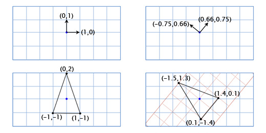
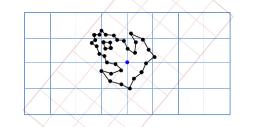
We showed how the coordinates of the ship are displayed in a different coordinate grid with rotated axes (or "basis vectors"). This is convenient in our case, since it saves us from having to apply trigonometric transformations to each of the points of the ship model.
Every time we change the basis vectors (1, 0) and (0, 1) to (a, b) and (c, d), then the new coordinate of the point (x, y) can be found using the expression:
x (a, b) + y (c, d)
Usually the basis vectors are (1, 0) and (0, 1) and we just get x (1, 0) + y (0, 1) = (x, y), and there is no need to take care of this further. However, it is important to remember that we can use other basic vectors when we need it.
Matrices are like two-dimensional vectors. For example, a typical 2x2 matrix might look like this:
When you multiply a matrix by a vector, you add the scalar product of each row to the vector by which it is multiplied. For example, if we multiply the above matrix by the vector (x, y), then we get:
(a, c) • (x, y) + (b, d) • (x, y)
Being written differently, this expression looks like this:
x (a, b) + y (c, d)
Looks familiar, isn't it? This is exactly the same expression that we used to change the basis vectors. This means that by multiplying the 2x2 matrix by a two-dimensional vector, we thereby change the basis vectors. For example, if we insert the standard basis vectors in (1, 0) and (0, 1) into the columns of the matrix, then we get:
This is the identity matrix that does not give the effect that we can expect from the neutral basis vectors that we have indicated. If, however, we rotate the base vectors by 49 degrees, we get:
This matrix will rotate the 2D vector 49 degrees counterclockwise. We can make the code of our game Asteriods more elegant using matrices like this. For example, the rotation function of our ship might look like this:
However, our code will be even more elegant if we can also include in this matrix the movement of the ship in space. Then we will have a single data structure that will contain and apply information about the orientation of the object and its location in space.
Fortunately, there is a way to achieve this, even though it does not look very elegant. If we want to move using the vector (e, f), we only include it in our transformation matrix:
And we add an additional unit to the end of each vector defining the location of the object, like this:
[xy 1]
Now, when we multiply them, we get:
(a, c, e) • (x, y, 1) + (b, d, f) • (x, y, 1) + (0, 0, 1) • (x, y, 1)
Which, in turn, can be written as:
x (a, b) + y (c, d) + (e, f)
Now we have a complete transformation mechanism, enclosed in a single matrix. This is important if you do not take into account the elegance of the code, since with it we can now use all the standard matrix manipulations. For example, multiply the matrices to add the desired effect, or we can invert the matrix to get the exact opposite position of the object.
Matrices in three-dimensional space work the same way as in two-dimensional. I gave examples of two-dimensional vectors and matrices, since they are simply displayed using a display showing a two-dimensional image. We just need to define three columns for basis vectors, instead of two. If the basis vectors are (a, b, c), (d, e, f) and (g, h, i) then our matrix will look like this:
If we need to move (j, k, l), then we add an extra column and row, as we said before:
And we add one [1] to the vector, like this:
[xyz 1]
Since in our case we only have one axis of rotation (located on the display), the only thing we need to know is the angle. I mentioned this earlier, mentioning that we can use trigonometric functions to implement a two-dimensional rotation function like this:
More elegantly, this can be expressed in a matrix form. To determine the matrix, we can apply this function to the axes (1, 0) and (0, 1) for the angle Θ, and then include the resulting axes in the columns of our matrix. So let's start with the coordinate axis X (1, 0). If we apply our function to it, we get:
(1 * cos (Θ) - 0 * sin (Θ), 1 * sin (Θ) + 0 * cos (Θ)) = (cos (Θ), sin ())
Then, we include the coordinate axis Y (0, 1). We get:
(0 * cos (Θ) - 1 * sin (Θ), 0 * sin (Θ) + 1 * cos (Θ)) = (-sin (Θ), cos (Θ))
We include the obtained coordinate axes in the matrix, and we obtain a two-dimensional rotation matrix:
Apply this matrix to Suzanne , the monkey from the Blender graphics package. The angle of rotation Θ is 45 degrees clockwise.
As you can see, it works. But what if we need to rotate around a point other than (0, 0)?
For example, we want to rotate the monkey's head around a point located in its ear:
To do this, we can start by creating the translation matrix T, which moves the object from the starting point to the point of rotation in the ear of the monkey, and the rotation matrix R, to rotate the object around the starting point. Now, to rotate around a point in the ear, we can first move the point in the ear to the place of the initial point, by inverting the matrix T, written as T -1 . Then, we rotate the object around the starting point, using the R matrix, and then apply the T matrix to move the rotation point back to its original position.
Below is an illustration of each of the steps described:
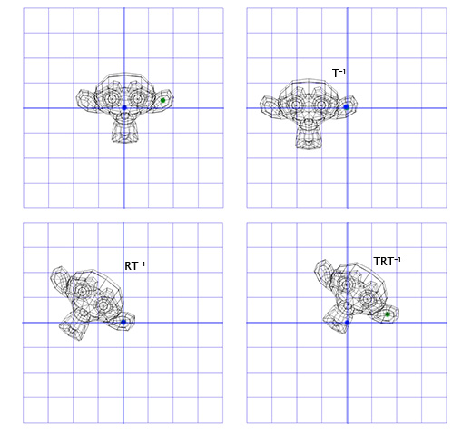
This is an important pattern that we will apply later - applying rotation to two opposite transformations allows us to rotate an object in another “space”. Which is very convenient and useful.
Now consider the three-dimensional rotation.
Rotation around the Z axis works on the same principle as rotation in two-dimensional space. We just need to change our old matrix by adding an additional column and row to it:
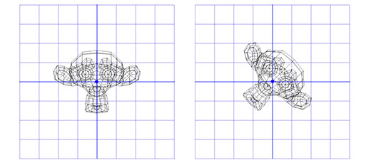
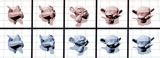
Apply this matrix to the three-dimensional version of Suzanne, the monkey from the Blender package. The angle of rotation Θ let it be equal to 45 degrees clockwise.
Same. Rotation only around the Z axis limits us, what about rotation around an arbitrary axis?
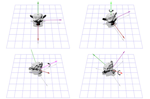
The representation of rotation defined by the axis and angle is also known as rotation in exponential coordinates, parametrized by the rotation of two quantities. The vector that determines the rotation of the guide axis (straight line) and the angle that describes the amount of rotation around this axis. Rotation is carried out according to the rule of the right hand .
So, rotation is defined by two parameters (axis, angle), where axis is the vector of the axis of rotation, and angle is the angle of rotation. This technique is quite simple and is a starting point for many other rotation operations that I work with. How to practically apply the rotation defined by the axis and angle?
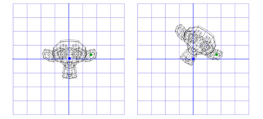
Suppose we are dealing with an axis of rotation shown in the figure below:
We know how to rotate an object around the Z axis, and we know how to rotate an object in other spaces. So, we just need to create a space where our axis of rotation will be the Z axis. And if this axis is the Z axis, then what will be the X and Y axes? Let's do the calculations now.
To create new X and Y axes, we only need to choose two vectors that are perpendicular to the new Z axis and perpendicular to each other. We have already spoken earlier about vector multiplication, which takes two vectors and gives as a result a vector perpendicular to them.
We have one vector now, this is the axis of rotation, let's call it A. Now let's take another random vector B, which is not in the same direction as vector A. Let it be (0, 0, 1) for example.
Now we have the rotation axis A and the random vector B, we can get the normal C through the vector product A and B. C is perpendicular to the vectors A and B. Now we make the vector B perpendicular to the vectors A and C through their vector product. And that's it, we have all the coordinate axes we need.
In words, it sounds difficult, but it looks pretty simple in code or when shown in pictures.
Below is what this looks like in code:
Here is an illustration for each step:
Now, having information about new coordinate axes, we can create a matrix M, including each axis as a column in this matrix. We need to make sure that vector A is the third column so that it is our new axis of coordinates Z.
Now this is similar to what we did to rotate in two-dimensional space. We can use the inverted matrix M to move to a new coordinate system, then rotate, according to the matrix R, to rotate the object around the Z axis, then apply the matrix M to return to the original coordinate space.
Now we can rotate the object around an arbitrary axis. In the end, we can simply create a matrix T = T = M -1 RM and use it many times, without additional efforts on our part. There are more efficient ways of converting rotations, defined by the axis and angle into rotation, defined by matrices. The approach we just described shows a lot of what we talked about earlier.
The rotation defined by the axis and angle is perhaps the most intuitive way. Applying it, it is very easy to invert the rotation by changing the sign at the corner, and it is easy to interpolate by interpolating the angle. However, there is a serious limitation, and it lies in the fact that such a rotation is not summing. That is, you cannot combine two rotations, defined by the axis and the angle to the third.
The rotation defined by the axis and the angle is a good way to start, but it must be transformed into something else in order to be used in more complex cases.
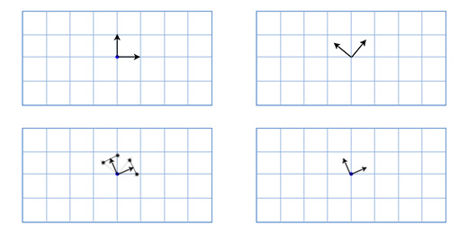
Euler angles represent another method of rotation, consisting in three nested rotations about the X, Y, and Z axes. You may have encountered their use in games where the camera shows the action from the first person, or from the third person.
Suppose you are playing a first-person shooter and you turned 30 degrees to the left and then looked 40 degrees up. In the end, you get shot, fall, and as a result of the impact, the camera rotates around its axis by 45 degrees. Below is shown the rotation using Euler angles (30, 40, 45).
Euler angles are a convenient and easy-to-manage tool. But this method has two drawbacks.
The first is the likelihood of a situation called “axle lock” or “hinge lock” (gimbal lock) . Imagine that you are playing a first-person shooter where you can look left, right, up and down, or turn the camera around the visual axis. Now imagine that you are looking straight up. In this situation, an attempt to look to the left or to the right will be similar to an attempt to rotate the camera. In this case, all we can do is rotate the camera around its axis, or look down. As you can imagine, this restriction makes it impractical to use Euler angles in flight simulators.
The second is that interpolation between two Euler angles of rotation does not give the shortest path between them.
For example, you have two interpolations between two identical rotations. The first uses the Euler angle interpolation, the second uses spherical linear interpolation (SLERP) to find the shortest path.
So, what is more suitable for interpolating rotations? Maybe matrices?
, . , . , - . , -:
, , , . , — , .
« » (candy wrapper effect), . Overgrowth ( . : ).

, , , , (gimbal lock), . . — .
, , , .
, . , , .
- ? , , (axis-angle rotation), .
, , (gimbal lock). - , , .
- , (rotation formats)?
. , , , . , .
- . , . -, , , .
, . , .
« » . , , , . , , .
«Bullet» «Blender» .
Why do we need linear algebra?
One of the directions in linear algebra is the study of vectors. If your game uses positioning of on-screen buttons, working with the camera and its direction, the speed of objects, then you will have to deal with vectors. The better you understand linear algebra, the more control you get over the behavior of vectors and, therefore, over your game.
What is a vector?
In games, vectors are used to store locations, directions, and speeds. Below is an example of a two-dimensional vector:
The location vector (also called the "radius vector") indicates that a person is two meters east and one meter north of the starting point. The speed vector shows that for a unit of time the plane moves three kilometers up and two miles to the left. The direction vector tells us that the gun is pointing right.
')
As you can see, the vector itself is just a set of numbers that takes on a particular meaning depending on the context. For example, a vector (1, 0) can be both a direction for a weapon, as shown in the picture, and coordinates of a building one mile east of your current position. Or the speed of the cochlea, which moves to the right at a speed of 1 mile per hour ( approx. Translator: rather quickly for a snail, 44 centimeters per second ).
It is important to track units. Suppose we have a vector V (3,5,2). This tells us little. Three what, five what? In our game, Overgrowth distances are indicated in meters and speeds in meters per second. The first number in this vector is the direction to the east, the second is the direction up, the third is the direction to the north. Negative numbers denote opposite directions, west, down, and south. The location defined by the vector V (3,5,2) is located three meters to the east, five meters above and two meters north, as shown in the image below.
So, we learned the basics of working with vectors. Now we learn how to use vectors.
Vector addition
To add vectors, we just need to add each of their components to each other. For example:
(0, 1, 4) + (3, -2, 5) = (0 + 3, 1-2, 4 + 5) = (3, -1, 9)
Why do we need to add vectors? Most often vector addition in games is used for physical integration. Any physical object will have vectors for location, speed, and acceleration. For each frame (usually one sixtieth of a second), we must integrate two vectors: add speed to location and acceleration to speed.
Let's look at the Mario jumping example. He starts from position (0, 0). At the moment of the start of the jump, his speed (1, 3), he quickly moves up and to the right. Its acceleration is (0, -1), as gravity pulls it down. The picture shows what his jump looks like, divided into seven frames. The black text shows its speed in each frame.
Let's take a look at the first frames in more detail in order to understand how everything happens.
For the first frame, we add Mario's speed (1, 3) to his location (0, 0) and get his new coordinates (1, 3). Then we add the acceleration (0, -1) with its speed (1, 3) and get the new value of the Mario speed (1, 2).
Do the same for the second frame. Add the speed (1, 2) to the location (1, 3) and get the coordinates (2, 5). Then we add acceleration (0, -1) to its speed (1, 2) and we get a new speed (1, 1).
Usually, the player controls the acceleration of the game character using the keyboard or gamepad, and the game, in turn, calculates new values for speeds and position using physical addition (through vector addition). This is the same problem that is solved in integral calculus , we just greatly simplify it for our game. I noticed that it was much easier for me to listen attentively to lectures on integral calculus, thinking about its practical application, which we have just described.
Subtract vectors
Subtraction is calculated according to the same principle as addition - we subtract the corresponding components of the vectors. Subtracting vectors is convenient for getting a vector that shows from one location to another. For example, let the player be located at the coordinates (1, 2) with a laser gun, and the enemy robot is located at the coordinates (4, 3). To determine the motion vector of the laser beam that will hit the robot, we need to subtract the player’s location from the robot’s location. We get:
(4, 3) - (1, 2) = (4-1, 3-2) = (3, 1).
Vector multiplication by scalar
When we talk about vectors, we call individual numbers scalars. For example (3, 4) is a vector, and 5 is a scalar. In games, it is often necessary to multiply a vector by a number (scalar). For example, simulating a simple air resistance by multiplying the player's speed by 0.9 in each frame. To do this, we need to multiply each component of the vector by a scalar. If the player’s speed is (10, 20), then the new speed will be:
0.9 * (10, 20) = (0.9 * 10, 0.9 * 20) = (9, 18).
Vector length
If we have a ship with a velocity vector V (4, 3), we will also need to find out how fast it is moving in order to calculate the need for screen space or how much fuel is needed. To do this, we need to find the length (modulus) of the vector V. The length of the vector is indicated by vertical lines, in our case the length of the vector V will be denoted as | V |.
We can represent V as a right triangle with sides 4 and 3 and, using the Pythagorean theorem, obtain the hypotenuse from the expression: x 2 + y 2 = h 2
In our case, the length of the vector H with the components (x, y) we get from the square root: sqrt (x 2 + y 2 ).
So, the speed of our ship is equal to:
| V | = sqrt (4 2 + 3 2 ) = sqrt (25) = 5
This approach is also used for three-dimensional vectors. The length of the vector with the components (x, y, z) is calculated as sqrt (x 2 + y 2 + z 2 )
Distance
If player P is at point (3, 3), and the explosion occurred at point E by coordinates (1, 2), we need to determine the distance between the player and the explosion in order to calculate the degree of damage caused to the player. This is easy to do by combining the two operations described above: subtracting vectors and their length.
We subtract P - E to get a vector between them. And then we determine the length of this vector, which gives us the desired distance. The order of the operands does not matter here, | E - P | will give the same result.
Distance = | P - E | = | (3, 3) - (1, 2) | = | (2, 1) | = sqrt (2 2 +1 2 ) = sqrt (5) = 2.23
Normalization
When we deal with directions (as opposed to locations and speeds), it is important that the direction vector has a length of one. This greatly simplifies our lives. For example, let's say the gun is turned in the direction (1, 0) and fires a projectile at a speed of 20 meters per second. What is the velocity vector for the projectile in this case?
Since the direction vector has a length equal to one, we multiply the direction by the velocity of the projectile and get the velocity vector (20, 0). If the same direction vector has a length other than one, we will not be able to do this. The projectile will be either too fast or too slow.
A vector with a length equal to one is called “normalized”. How to make a vector normalized? Pretty simple. We divide each component of the vector by its length. If, for example, we want to normalize a vector V with components (3, 4), we simply divide each component by its length, that is, by 5, and we get (3/5, 4/5). Now, using the Pythagorean theorem, we make sure that its length is equal to one:
(3/5) 2 + (4/5) 2 = 9/25 + 16/25 = 25/25 = 1
Dot product of vectors
What is a scalar product (written as •)? To calculate the scalar product of two vectors, we must multiply their components, and then add the results together
(a1, a2) • (b1, b2) = a1b1 + a2b2
For example: (3, 2) • (1, 4) = 3 * 1 + 2 * 4 = 11. At first glance it seems useless, but let's take a closer look at this:
Here we can see that if the vectors are pointing in one direction, then their scalar product is greater than zero. When they are perpendicular to each other, the scalar product is zero. And when they point in opposite directions, their scalar product is less than zero.
Basically, using the scalar product of vectors, you can calculate how many of them are pointing in one direction. And although this is only a small part of the capabilities of the scalar product, it is already very useful for us.
Suppose we have a guard, located in G (1, 3) looking in the direction of D (1,1), with a viewing angle of 180 degrees. The main character of the game is watching him from the position H (3, 2). How to determine whether the protagonist is in sight of the guard or not? We do this by the scalar product of vectors G and V (a vector directed from the guard to the main character). We will get the following:
V = H - G = (3, 2) - (1, 3) = (3-1, 2-3) = (2, -1)
D • V = (1, 1) • (2, -1) = 1 * 2 + 1 * -1 = 2-1 = 1
Since the unit is greater than zero, the main character is in the field of view of the guard.
We already know that the scalar product is related to determining the direction of vectors. And what is its more precise definition? The mathematical expression of the scalar product of vectors is as follows:
A • B = | A || B | cosΘ
Where Θ (pronounced "theta") is the angle between vectors A and B.
This allows us to find Θ (angle) using the expression:
Θ = acos ([AB] / [| A || B |])
As I said earlier, normalizing vectors simplifies our lives. And if A and B are normalized, the expression is simplified as follows:
Θ = acos (AB)
Let's look again at the scenario with the guard. Let now the angle of view of the guard will be equal to 120 degrees. We obtain the normalized vectors for the direction of the guard's look (D ') and for the direction from the guard to the protagonist (V'). Then we define the angle between them. If the angle is more than 60 degrees (half of the viewing angle), then the main character is out of sight of the guard.
D '= D / | D | = (1, 1) / sqrt (1 2 + 1 2 ) = (1, 1) / sqrt (2) = (0.71, 0.71)
V '= V / | V | = (2, -1) / sqrt (2 2 + (-1) 2 ) = (2, -1) / sqrt (5) = (0.89, -0.45)
Θ = acos (D'V ') = acos (0.71 * 0.89 + 0.71 * (- 0.45)) = acos (0.31) = 72
The angle between the center of the field of view of the guard and the location of the main character is 72 degrees, hence the guard does not see him.
I understand that it looks quite difficult, but this is because we do everything manually. The program is all pretty simple. Below is shown how I did it in our Overgrowth game with the help of C ++ libraries I wrote for working with vectors:
// vec2 guard_pos = vec2(1,3); vec2 guard_facing = vec2(1,1); vec2 hero_pos = vec2(3,2); // vec2 guard_facing_n = normalize(guard_facing); vec2 guard_to_hero = normalize(hero_pos - guard_pos); // float angle = acos(dot(guard_facing_n, guard_to_hero)); Vector product
Suppose we have a ship with guns that shoot right and left along the course. Assume that the boat is located along the direction vector (2, 1). In what directions are guns firing now?
It is quite simple in 2D graphics. To rotate the direction 90 degrees clockwise, simply swap the components of the vector, and then swap the sign of the second component.
(a, b) turns into (b, -a). Consequently, for a ship located along the vector (2, 1), the cannons on the right along the board will fire in the direction (1, -2), and the guns from the left side will fire in the opposite direction. Change the signs of the components of the vector and get (-1, 2).
And what if we want to calculate this all for three-dimensional graphics? Consider the ship example.
We have the vector of the mast M directed straight up (0, 1, 0) and the wind direction: north-northeast W (1, 0, 2). And we want to calculate the direction vector of the sail S in order to “catch the wind” in the best way.
To solve this problem, we use the vector product: S = M x W.
The vector product A (a 1 , a 2 , a 3 ) and B (b 1 , b 2 , b 3 ) will be equal to:
(a 2 b 3 -a 3 b 2 , a 3 b 1 -a 1 b 3 , a 1 b 2 -a 2 b 1 )
Now we substitute the values we need:
S = MxW = (0, 1, 0) x (1, 0, 2) = ([1 * 2 - 0 * 0], [0 * 1 - 0 * 2], [0 * 0 - 1 * 1] ) = (2, 0, -1)
For manual calculations it is quite difficult, but for graphics and gaming applications, I recommend writing a function similar to the one below and not going into details of such calculations.
vec3 cross(vec3 a, vec3 b) { vec3 result; result[0] = a[1] * b[2] - a[2] * b[1]; result[1] = a[2] * b[0] - a[0] * b[2]; result[2] = a[0] * b[1] - a[1] * b[0]; return result; } Vector artwork is often used in games to calculate surface normals. Directions in which this or that surface "looks". For example, consider a triangle with vectors A, B, and C. How do we find the direction in which the triangle "looks", that is, the direction perpendicular to its plane? It seems difficult, but we have a tool for solving this problem.
Use subtraction to determine the direction from A to C (C - A), let it be “face 1” (Edge 1) and the direction from A to B (B - A), let it be “face 2” (Edge 2) . And then we apply the vector product to find a vector perpendicular to both of them, that is, perpendicular to the plane of the triangle, also called the "normal to the plane."
This is what the code looks like:
vec3 GetTriangleNormal(vec3 a, vec3 b, vec3 c) { vec3 edge1 = ba; vec3 edge2 = ca; vec3 normal = cross(edge1,edge2); return normal; } In games, the basic expression of illuminance is written as N • L, where N is the normal to the illuminated surface, and L is the normalized vector of the direction of light. As a result, the surface looks bright when light directly falls on it, and dark when it does not occur.
We now turn to the consideration of such an important concept for game developers as the "transformation matrix" (transformation matrix).
To begin, examine the "building blocks" of the transformation matrix.
Basic vector
Suppose we write the game Asteroids on a very old "hardware" and we need a simple two-dimensional spacecraft that can freely rotate in its plane. The ship model looks like this:
How do we draw a ship when the player turns it to an arbitrary degree, say 49 degrees counterclockwise. Using trigonometry, we can write a two-dimensional rotation function that takes the coordinates of a point and the angle of rotation, and returns the coordinates of the offset point:
vec2 rotate(vec2 point, float angle){ vec2 rotated_point; rotated_point.x = point.x * cos(angle) - point.y * sin(angle); rotated_point.y = point.x * sin(angle) + point.y * cos(angle); return rotated_point; } Applying this function to all three points, we get the following picture:
Operations with sines and cosines work rather slowly, but since we only make calculations for three points, it will work fine even on the old “hardware” ( note of the translator: in cases when it is intended to use trigonometric functions intensively, to speed up the calculations, Memory organizes tables of values for each function and calculates them when the application is started. Then, when calculating a particular trigonometric function, the table is simply referenced .
Let now our ship looks like this:
Now the old approach will be too slow, since it will be necessary to turn a fairly large number of points. One of the elegant solutions to this problem will sound like this: “What if, instead of turning each point of the ship model, we turn the coordinate grid of our model?”
How it works? Let's take a closer look at what the coordinates are.
When we talk about a point with coordinates (3, 2), we say that its location is three steps from the point of reference on the coordinate axis X, and two steps from the point of reference on the coordinate axis Y.
By default, the coordinate axes are arranged as follows: the vector of the coordinate axis X (1, 0), the vector of the coordinate axis Y (0, 1). And we get the location: 3 (1, 0) + 2 (0, 1). But coordinate axes do not have to be in this position. If we rotate the coordinate axes, at this time we rotate all points in the coordinate lattice.
To get the rotated X and Y axes, we will use the trigonometric functions that we talked about above. If we rotate by 49 degrees, the new coordinate axis X will be obtained by rotating the vector (0, 1) 49 degrees, and the new coordinate axis Y will be obtained by rotating the vector (0, 1) 49 degrees. So, the vector of the new X axis will be equal to (0.66, 0.75), and the vector of the new Y axis will be (-0.75, 0.66). We do this manually for our simple three-point model to make sure that it works as it should:
The coordinates of the top point (0, 2), which means that its new location is at 0 on the new (rotated) X axis and 2 on the new Y axis:
0 * (0.66,0.75) + 2 * (- 0.75, 0.66) = (-1.5, 1.3)
The lower left point is (-1, -1), which means that its new location is -1 on the rotated X axis, and -1 on the rotated Y axis:
-1 * (0.66,0.75) + -1 * (- 0.75, 0.66) = (0.1, -1.4)
Lower right point (1, -1), which means its new location is 1 on the rotated X axis, and -1 on the rotated Y axis
1 * (0.66,0.75) + -1 * (- 0.75, 0.66) = (1.4, 0.1)
We showed how the coordinates of the ship are displayed in a different coordinate grid with rotated axes (or "basis vectors"). This is convenient in our case, since it saves us from having to apply trigonometric transformations to each of the points of the ship model.
Every time we change the basis vectors (1, 0) and (0, 1) to (a, b) and (c, d), then the new coordinate of the point (x, y) can be found using the expression:
x (a, b) + y (c, d)
Usually the basis vectors are (1, 0) and (0, 1) and we just get x (1, 0) + y (0, 1) = (x, y), and there is no need to take care of this further. However, it is important to remember that we can use other basic vectors when we need it.
Matrices
Matrices are like two-dimensional vectors. For example, a typical 2x2 matrix might look like this:
[acbd]
When you multiply a matrix by a vector, you add the scalar product of each row to the vector by which it is multiplied. For example, if we multiply the above matrix by the vector (x, y), then we get:
(a, c) • (x, y) + (b, d) • (x, y)
Being written differently, this expression looks like this:
x (a, b) + y (c, d)
Looks familiar, isn't it? This is exactly the same expression that we used to change the basis vectors. This means that by multiplying the 2x2 matrix by a two-dimensional vector, we thereby change the basis vectors. For example, if we insert the standard basis vectors in (1, 0) and (0, 1) into the columns of the matrix, then we get:
 [ten
  0 1]
This is the identity matrix that does not give the effect that we can expect from the neutral basis vectors that we have indicated. If, however, we rotate the base vectors by 49 degrees, we get:
 [0.66 -0.75
  0.75 0.66]
This matrix will rotate the 2D vector 49 degrees counterclockwise. We can make the code of our game Asteriods more elegant using matrices like this. For example, the rotation function of our ship might look like this:
void RotateShip(float degrees){ Matrix2x2 R = GetRotationMatrix(degrees); for(int i=0; i<num_points; ++i){ rotated_point[i] = R * point[i]; } } However, our code will be even more elegant if we can also include in this matrix the movement of the ship in space. Then we will have a single data structure that will contain and apply information about the orientation of the object and its location in space.
Fortunately, there is a way to achieve this, even though it does not look very elegant. If we want to move using the vector (e, f), we only include it in our transformation matrix:
[acebdf 0 0 1]
And we add an additional unit to the end of each vector defining the location of the object, like this:
[xy 1]
Now, when we multiply them, we get:
(a, c, e) • (x, y, 1) + (b, d, f) • (x, y, 1) + (0, 0, 1) • (x, y, 1)
Which, in turn, can be written as:
x (a, b) + y (c, d) + (e, f)
Now we have a complete transformation mechanism, enclosed in a single matrix. This is important if you do not take into account the elegance of the code, since with it we can now use all the standard matrix manipulations. For example, multiply the matrices to add the desired effect, or we can invert the matrix to get the exact opposite position of the object.
Three-dimensional matrix
Matrices in three-dimensional space work the same way as in two-dimensional. I gave examples of two-dimensional vectors and matrices, since they are simply displayed using a display showing a two-dimensional image. We just need to define three columns for basis vectors, instead of two. If the basis vectors are (a, b, c), (d, e, f) and (g, h, i) then our matrix will look like this:
[adgbehcfi]
If we need to move (j, k, l), then we add an extra column and row, as we said before:
[adgjbehkcfil 0 0 0 1]
And we add one [1] to the vector, like this:
[xyz 1]
Rotation in two-dimensional space
Since in our case we only have one axis of rotation (located on the display), the only thing we need to know is the angle. I mentioned this earlier, mentioning that we can use trigonometric functions to implement a two-dimensional rotation function like this:
vec2 rotate(vec2 point, float angle){ vec2 rotated_point; rotated_point.x = point.x * cos(angle) - point.y * sin(angle); rotated_point.y = point.x * sin(angle) + point.y * cos(angle); return rotated_point; } More elegantly, this can be expressed in a matrix form. To determine the matrix, we can apply this function to the axes (1, 0) and (0, 1) for the angle Θ, and then include the resulting axes in the columns of our matrix. So let's start with the coordinate axis X (1, 0). If we apply our function to it, we get:
(1 * cos (Θ) - 0 * sin (Θ), 1 * sin (Θ) + 0 * cos (Θ)) = (cos (Θ), sin ())
Then, we include the coordinate axis Y (0, 1). We get:
(0 * cos (Θ) - 1 * sin (Θ), 0 * sin (Θ) + 1 * cos (Θ)) = (-sin (Θ), cos (Θ))
We include the obtained coordinate axes in the matrix, and we obtain a two-dimensional rotation matrix:
 [cos (Θ) -sin (Θ)
  sin (Θ) cos (Θ)]
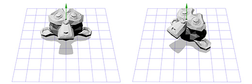
Apply this matrix to Suzanne , the monkey from the Blender graphics package. The angle of rotation Θ is 45 degrees clockwise.
As you can see, it works. But what if we need to rotate around a point other than (0, 0)?
For example, we want to rotate the monkey's head around a point located in its ear:
To do this, we can start by creating the translation matrix T, which moves the object from the starting point to the point of rotation in the ear of the monkey, and the rotation matrix R, to rotate the object around the starting point. Now, to rotate around a point in the ear, we can first move the point in the ear to the place of the initial point, by inverting the matrix T, written as T -1 . Then, we rotate the object around the starting point, using the R matrix, and then apply the T matrix to move the rotation point back to its original position.
Below is an illustration of each of the steps described:
This is an important pattern that we will apply later - applying rotation to two opposite transformations allows us to rotate an object in another “space”. Which is very convenient and useful.
Now consider the three-dimensional rotation.
3D rotation
Rotation around the Z axis works on the same principle as rotation in two-dimensional space. We just need to change our old matrix by adding an additional column and row to it:
 [cos (Θ) -sin (Θ) 0
  sin (Θ) cos (Θ) 0
  0 0 1]
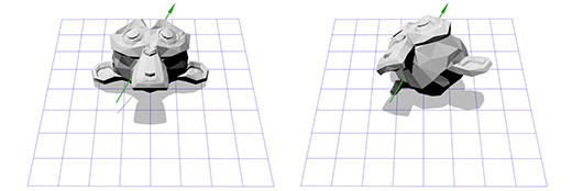
Apply this matrix to the three-dimensional version of Suzanne, the monkey from the Blender package. The angle of rotation Θ let it be equal to 45 degrees clockwise.
Same. Rotation only around the Z axis limits us, what about rotation around an arbitrary axis?
The rotation defined by the axis and angle (Axis-angle rotation)
The representation of rotation defined by the axis and angle is also known as rotation in exponential coordinates, parametrized by the rotation of two quantities. The vector that determines the rotation of the guide axis (straight line) and the angle that describes the amount of rotation around this axis. Rotation is carried out according to the rule of the right hand .
So, rotation is defined by two parameters (axis, angle), where axis is the vector of the axis of rotation, and angle is the angle of rotation. This technique is quite simple and is a starting point for many other rotation operations that I work with. How to practically apply the rotation defined by the axis and angle?
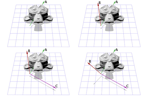
Suppose we are dealing with an axis of rotation shown in the figure below:
We know how to rotate an object around the Z axis, and we know how to rotate an object in other spaces. So, we just need to create a space where our axis of rotation will be the Z axis. And if this axis is the Z axis, then what will be the X and Y axes? Let's do the calculations now.
To create new X and Y axes, we only need to choose two vectors that are perpendicular to the new Z axis and perpendicular to each other. We have already spoken earlier about vector multiplication, which takes two vectors and gives as a result a vector perpendicular to them.
We have one vector now, this is the axis of rotation, let's call it A. Now let's take another random vector B, which is not in the same direction as vector A. Let it be (0, 0, 1) for example.
Now we have the rotation axis A and the random vector B, we can get the normal C through the vector product A and B. C is perpendicular to the vectors A and B. Now we make the vector B perpendicular to the vectors A and C through their vector product. And that's it, we have all the coordinate axes we need.
In words, it sounds difficult, but it looks pretty simple in code or when shown in pictures.
Below is what this looks like in code:
B = (0,0,1); C = cross(A,B); B = cross(C,A); Here is an illustration for each step:
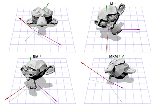
Now, having information about new coordinate axes, we can create a matrix M, including each axis as a column in this matrix. We need to make sure that vector A is the third column so that it is our new axis of coordinates Z.
 [B0 C0 A0
  B1 C1 A1
  B2 C2 A2]
Now this is similar to what we did to rotate in two-dimensional space. We can use the inverted matrix M to move to a new coordinate system, then rotate, according to the matrix R, to rotate the object around the Z axis, then apply the matrix M to return to the original coordinate space.
Now we can rotate the object around an arbitrary axis. In the end, we can simply create a matrix T = T = M -1 RM and use it many times, without additional efforts on our part. There are more efficient ways of converting rotations, defined by the axis and angle into rotation, defined by matrices. The approach we just described shows a lot of what we talked about earlier.
The rotation defined by the axis and angle is perhaps the most intuitive way. Applying it, it is very easy to invert the rotation by changing the sign at the corner, and it is easy to interpolate by interpolating the angle. However, there is a serious limitation, and it lies in the fact that such a rotation is not summing. That is, you cannot combine two rotations, defined by the axis and the angle to the third.
The rotation defined by the axis and the angle is a good way to start, but it must be transformed into something else in order to be used in more complex cases.
Euler angles
Euler angles represent another method of rotation, consisting in three nested rotations about the X, Y, and Z axes. You may have encountered their use in games where the camera shows the action from the first person, or from the third person.
Suppose you are playing a first-person shooter and you turned 30 degrees to the left and then looked 40 degrees up. In the end, you get shot, fall, and as a result of the impact, the camera rotates around its axis by 45 degrees. Below is shown the rotation using Euler angles (30, 40, 45).
Euler angles are a convenient and easy-to-manage tool. But this method has two drawbacks.
The first is the likelihood of a situation called “axle lock” or “hinge lock” (gimbal lock) . Imagine that you are playing a first-person shooter where you can look left, right, up and down, or turn the camera around the visual axis. Now imagine that you are looking straight up. In this situation, an attempt to look to the left or to the right will be similar to an attempt to rotate the camera. In this case, all we can do is rotate the camera around its axis, or look down. As you can imagine, this restriction makes it impractical to use Euler angles in flight simulators.
The second is that interpolation between two Euler angles of rotation does not give the shortest path between them.
For example, you have two interpolations between two identical rotations. The first uses the Euler angle interpolation, the second uses spherical linear interpolation (SLERP) to find the shortest path.
So, what is more suitable for interpolating rotations? Maybe matrices?
Rotation using matrices
, . , . , - . , -:
, , , . , — , .
« » (candy wrapper effect), . Overgrowth ( . : ).
, , , , (gimbal lock), . . — .
, , , .
, . , , .
- ? , , (axis-angle rotation), .
, , (gimbal lock). - , , .
- , (rotation formats)?
. , , , . , .
- . , . -, , , .
, . , .
« » . , , , . , , .
«Bullet» «Blender» .
Source: https://habr.com/ru/post/131931/
All Articles