DIY preamp in A class. Clone Lehmann BCL
Greetings After buying the headphones, the issue of quality amplification began to mature for them, and I began to choose the appropriate options, I rejected the factory solutions immediately, due to the overpriced price and cheap enough element base. The choice fell on DIY options. Then a preamp became necessary for a power amplifier and I set about assembling. My choice was on a clone of Lehmann BCL, the original version is quite well known, has a decent sound, a large number of people in foreign forums repeated this design. But the amplifier is very sensitive to the quality of the element base, so the components were used the best that I could reach. The entire amplifier is assembled from parts purchased on ebay. Please forgive me, but some photos are a bit outdated, under them I'll write what has changed so far, let's begin!
Some technical specifications
- Frequency range: 10-35000 Hz
- Input impedance: 47 kΩ
- S / N ratio: 95 dB at 0 dB gain (Gain switches: 0dB + 10dB + 18dB + 20dB)
- Output power: 200 mW / 300 ohm 400 mW / 60 ohm
- Distortion: <0.001% at 6 mW at 300 ohms
- Headphone impedance: 32 to 600 ohms
Build, configure

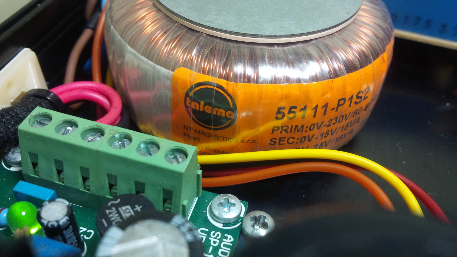
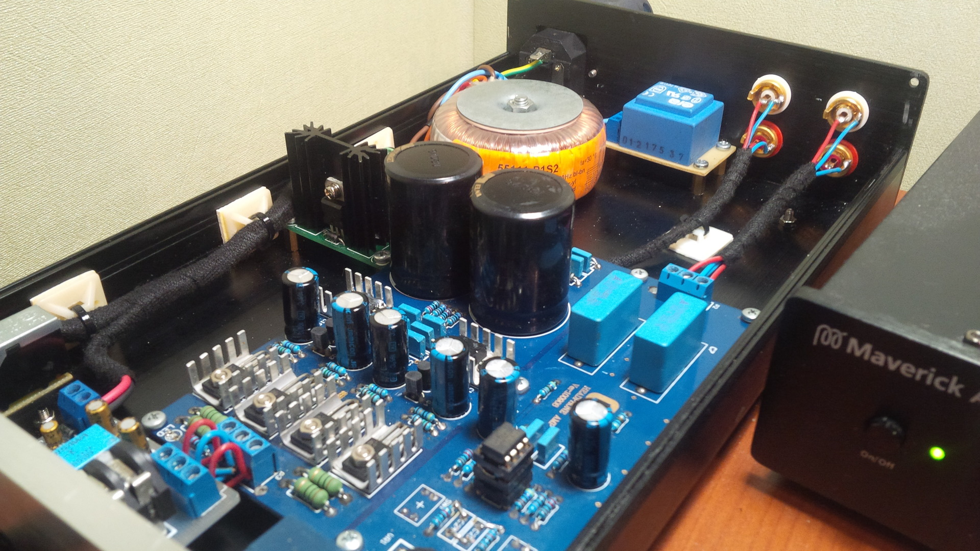
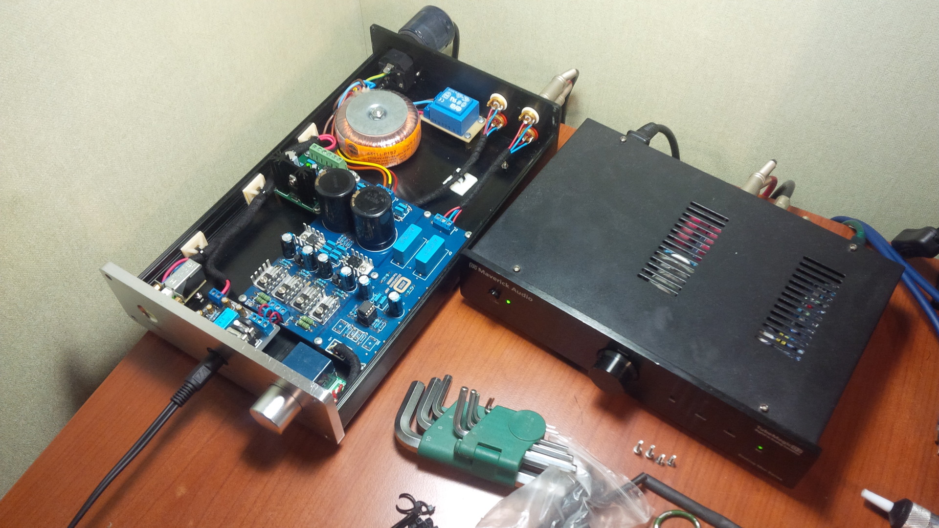
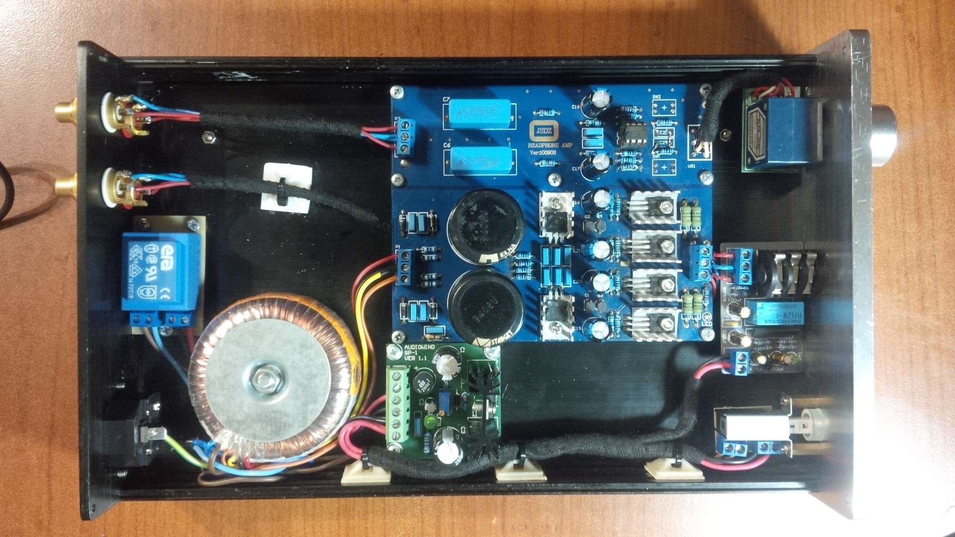
First, I bought a factory amplifier board, on ebay the Chinese are sold in bundles, I didn’t poison it, the amplifier is very sensitive to wiring, and if the layout is incorrect, the board starts to fade, and this board is multi-layered, double-sided, with gilding of the holes. Output transistors are selected in pairs. Capacitors Samwha, elna, rubycon, epcos, wima. Resistors used 1% accuracy. Potentiometer –Japanese Alps, chose it because it has an almost perfect channel balance for potentiometers, the divergence between the channels by ear is not distinguishable, it can change to DACT over time, but it will cost as half of the amplifier :) As a signal relay in protection used relay from Takamisawa with gold-plated contacts. The protection provides as well as the load disconnection at the appearance of a constant voltage at the output, as well as a five second switch-on delay. The protection is switched on from a separate stabilized power source, which excludes its effect on the amplifier power supply and ensures that the protection will function if the power supply of the amplifier breaks down. Transformer Czech firm Talema. The second, P shaped already replaced, on the quality of the fill. Opa 2134 operational amplifier, transferred to class A, loaded with resistors, it would be more correct than jfet cascade, but for now, as time and desire will, I will. Bringing down the switching of the gains (0dB + 10dB + 18dB + 20dB) can be adjusted precisely to your headphones to avoid sharp and very smooth volume additions.
')
The photos have not yet connected a linear output, it is connected from the headphone output, through 48 ohm resistors.
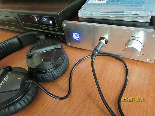
The design cost 12-13 thousand rubles, it is quite inexpensive when compared with the factory versions. Now pleases me with its sound. It works with Technics sl-pg480a and sennheiser hd280, I’ll soon plan to replace the headphones with something more serious. Now it works as a headphone amplifier and as a preamp for a booster (If necessary, I'll write more about it, too)
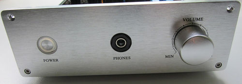
The finished product :)


If I miss something important, ask in the comments, I will add an article.
At the request of commenting
Scheme:
Amplifier: circuit01a.jpg
Power supply: circuit02a.jpg
Where can one buy?
Fee: Headphone Amplifier kit Diy Base on Lehmann AMP Circuit
Case: DIY Aluminum Headphone Amplifier Case Amp Enclosure
Transformer: 220V / 115v 30W R-Core Transformer for preamp 9V * 2 15V * 2
Listings on ebay will not exist for a long time, I indicated the name on the links, then it will be possible to find it in the search.
UPD: 02.16.2016
Now working in tandem with the Maverick Audio D2 + Sennheiser HD650.
Since 2011, the amplifier has received a number of upgrades and improvements:
- Replaced the internal wiring of power from the Chinese to PuGv, the signal was also replaced with noname to clotz.
- The U-shaped transformer is replaced by a transformer in the potting, it is mounted on the circuit board directly behind the main toroidal transformer. Printed circuit board for transformer era 220V primary, 9V secondary: pcb_transformer
- The samwha capacitors swelled and were replaced with simple jamicon, maybe later I'll bother and change it to something from audio-grade.
- Raised current opamp to 5mA. lovelycubeclassabiasmod
- Changed RCA connectors for decent.
- Packed all amplifier wiring in tesa heat-resistant tape.
- I connected the line output and actively use the amplifier as a preamplifier.
- I changed the display from blue to pleasant green (my eyes became less tired at night).
Source: https://habr.com/ru/post/131922/
All Articles