Retrieving data from a MEMS gyro (part I)
Introduction
The main goal at this stage was to obtain data from the MEMS gyro connected to the breadboard through the I2C bus. In this article I would like to tell you what happened. Who cares please under the cat (careful traffic).
What it took to purchase
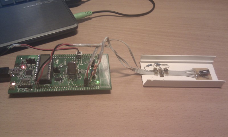
- Development Board STM32L-DISCOVERY
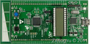
Why did the choice fall on her? Because it was a ratio of pretty optimal price and its capabilities available at that time.
- MEMS gyro L3G4200D
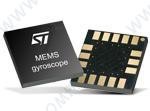
Among the three axial gyroscopes there was no particular choice therefore they took this one, since the essence was for the time being just to study what and how it works, that was quite enough.
- A pair of capacitors and resistors
What for this had to do
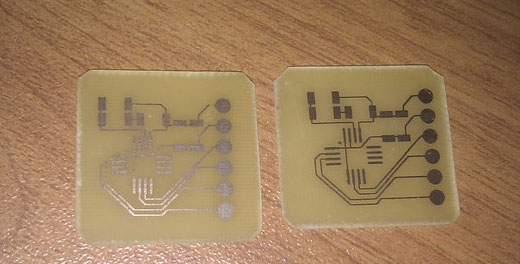
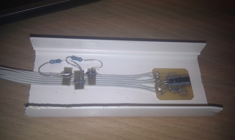
- Design board for MEMS gyro

To connect the gyroscope it was required to make a printed circuit board for connection via the I2C bus according to the Datasheet.
')
- Make it (just two just in case)
- Solder MEMS gyro in the stove

- Solder capacitors, resistors and cables
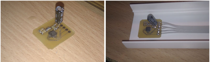
- At this stage, I remembered that I2C required pull-up resistors for power, I had to ignore the aesthetic appearance: (it turned out like this:
- It remains to connect to the breadboard board power and I2C cable
What for it it was necessary to implement programmatically
- Receiving data from the gyroscope on the interruption to the prototype board via the I2C bus, for this it was required to use the library "Stm32 peripheral library"
- Transferring data to a computer: a mock-up board is defined as a HID device and provides the computer with a generated data packet from a gyroscope; for this, the STM32L1xx USB full-speed device library was used.
- Receiving data on a computer from a HID device, a PC application was written in C # and a library was needed that would help communicate with the HID device, the GNU project USB Generic HID Communications 2_0_0_0 helped us with this
What is the result?
- In one case, the integration of data from the gyroscope directly on the breadboard controller was realized and the further transfer of the angle values to the computer, below is an example video:
- In fact, the data from the gyroscope is very noisy and requires thorough mathematical processing.
- Now, for a more detailed analysis, raw data from the gyroscope is received on the computer, here’s how they look:
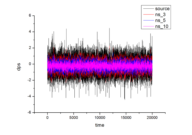 Here, black shows raw data and three methods for obtaining a moving average (red, blue and purple), the gyroscope is at rest
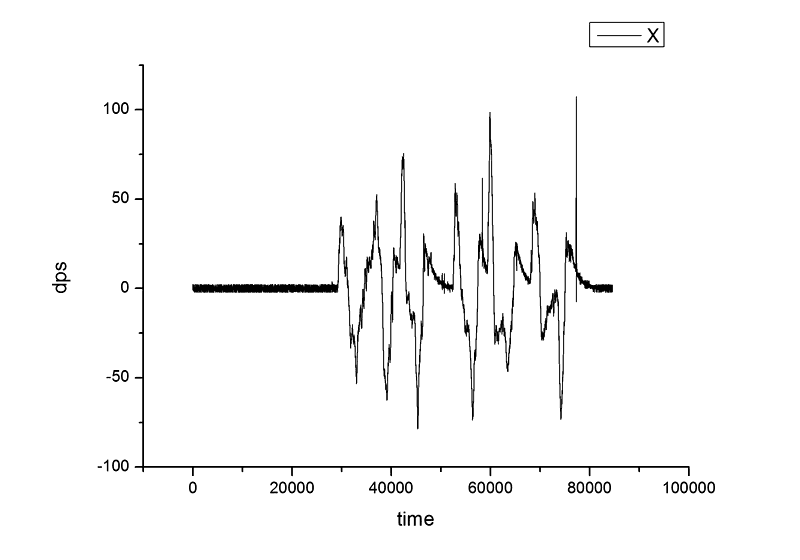 Data from the X axis, the gyroscope rotates
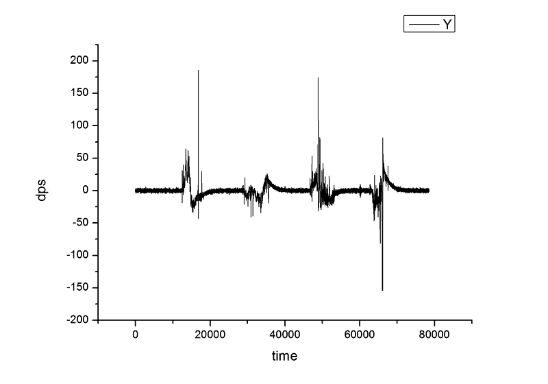 Data from the Y axis, the gyroscope rotates
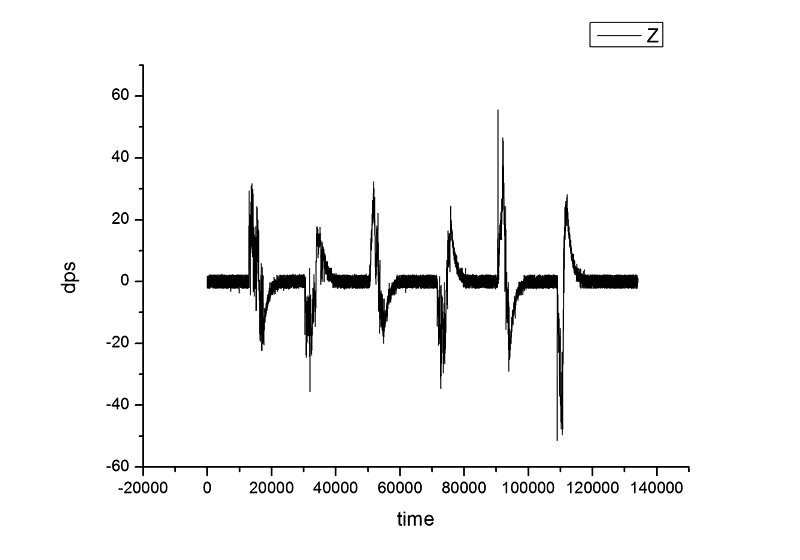 Data from the Z axis, the gyroscope rotates
Conclusion
In conclusion, I would like to say that work on the project is still going on and I would like to get more accurate values from the gyroscope by applying various filters, get rid of noise and better integrate the data so that I can finally get the gyroscope orientation angles. If anyone has any advice on this matter, I will be happy to hear them. In the next part I will try to talk about what happened with the processing of this data. Thank you all for your attention.Source: https://habr.com/ru/post/131502/
All Articles