Six-power life on the tail of a python
Continuing the cycle of articles modeling parallel mechanisms using the Arduino hardware platform and various improvised trash ( Catching the horizon with the Arduino , Three-power Arduino manipulator ), today we should pay attention to managing the six-power platform using Python from the Linux operating system.
In previous posts, I talked about the prospect of creating a mockup of the six-power Stuart platform. And so all the components came from distant China, and also assembled on the table, you can proceed!
')
Development of previous layouts was done using a laptop with Windows 7 operating system, with Visual Studio 2008 installed. All programming was done in C # with the Microsoft .NET Framework library.
Since the main machine for working and performing everyday tasks is a stationary computer with the Ubuntu Linux 10.4 operating system installed, it was decided to master the interaction in Python with Arduino. Why not equip yourself with the experience of working with hardware from various environments;)
To work we need the following tools and materials:
From the software you need:
The scope of mechanisms with different degrees of freedom, which are based on parallel kinematic connections is very wide:
The scalability of such mechanisms makes it easy to build large-scale units with high speed on their basis, and large construction accelerations are used to create various industrial robots or platforms, for example, for telescopes, lasers, telecommunication antennas or jet engines.
A detailed description of working with servos is described in my article about a three-power platform , in this case, instead of three drives, six are used, the layout corresponds to the Stewart platform.
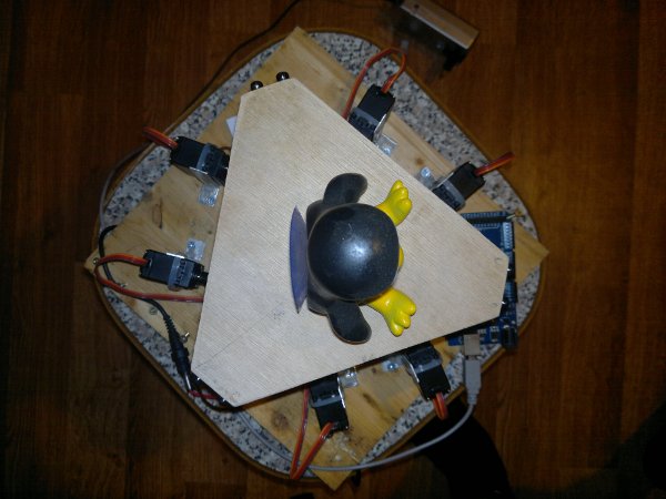
In order not to break the platform in critical positions or under load, the work colleague (many thanks to Michael) suggested using ordinary rods from helium pens as connecting parts, and a ball bearing from a helicopter as docking units.
Top view of the platform after assembly:
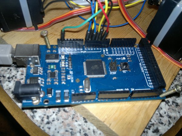
Servo drives are controlled using PWM, respectively, with 2-7 outputs of the Arduino Mega:
And inside, under the platform, the servas are connected in the usual way on a breadboard:
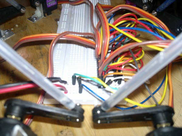
In the general case, we simply doubled the number of components relative to the three-power scheme and put them into one, rather stable construction. It is important to fix the ball bearings on the rods with glue, because during many tests the joints are simply annoying.
The concept of six degrees of freedom on Wikipedia has the following definition:
Graphically, this definition can be displayed as follows ( source )

Based on this, we obtain that the six degrees of freedom are:
An example of a rotation around the axis X - roll of the vessel ( source ):
An example of a rotation around the Y axis - vessel pitch ( source ):

An example of a rotation around the Z axis is the yaw of a vessel ( source ):
On the Internet there are many examples of describing degrees of rotation around the axes, here is one of them .
After assembling the layout, as well as modifying the control program for the three servos, the format of the control command is as follows:

The control command consists of 1 byte of the command prefix; in our case, the character 'S' will be used, and six drive positions of two bytes each. How to form such a command using the C language is immediately clear: declare the structure of the corresponding format. In Python, the “battery pack” has a wonderful struct module for forming a string from a set of fields.
The structure presented above in terms of the module struct is as follows:
According to the module documentation:
All primary tests can be performed in the Python console, in our case we use the powerful IPython tool, and to connect to the hardware we will need the Serial library.
Connection to the platform is as follows:
Sending data after a successful connection and opening the port is performed as follows:
This code will form the basis of the testing procedures for the platform, as well as for the platform control program using the joystick.
To automatically test all degrees of freedom, you can use the following simple procedures in Python:
The easiest way to get values from the “pleasure stick” is to use the PyGame module. This module is based on SDL and has many convenient tools for developing toys in Python, and it also includes tools for working with game controllers.

A simple example of initializing a joystick and getting coordinates:
The platform control program with a joystick has a graphical interface thanks to the PyQt4 library, although at first there was a burning desire to make it on curses (which was almost implemented). When the joystick is connected and the port for working with the board is open, the timer sends data via a 33 ms interval from the game controller and transfers it to the board.
Management Interface:

Note: I just want to make a reservation that the joystick is cheap, so it has a lot of dead zones and disgusting sensitivity, and the platform is on “fast” servers, so the edges of the joystick are immediately visible.
As a result of testing the program turned out the following video:
As a result of the work done, we achieved the following results.
The main problems for the future, in the solution of which your comments can often help:
PS: I do not speak as an innovator in this area, I welcome any suggestions and criticism.
In previous posts, I talked about the prospect of creating a mockup of the six-power Stuart platform. And so all the components came from distant China, and also assembled on the table, you can proceed!
')
Tools and materials
Development of previous layouts was done using a laptop with Windows 7 operating system, with Visual Studio 2008 installed. All programming was done in C # with the Microsoft .NET Framework library.
Since the main machine for working and performing everyday tasks is a stationary computer with the Ubuntu Linux 10.4 operating system installed, it was decided to master the interaction in Python with Arduino. Why not equip yourself with the experience of working with hardware from various environments;)
To work we need the following tools and materials:
| Renaming | amount |
| Aggregate with installed Linux | 1 PC. |
| Six-power platform | 1 PC. |
| Arduino mega | 1 PC. |
| Bread board | 1 PC. |
| Screed | 6 pieces |
| Servos | 6 pieces |
| Corners | 6 pieces |
| Ball bearings | 12 pcs. |
| Rods from helium pens | 6 pieces |
| Connecting wires | 20 pcs. |
| Penguin + scotch | 1 PC. |
| Joystick | 1 PC. |
From the software you need:
- Linux
- Arduino 0022
- Python
- Ipython
- Pygame
- PySerial
- PyQt4
We assemble the platform
The scope of mechanisms with different degrees of freedom, which are based on parallel kinematic connections is very wide:
- multi-axis milling and drilling machines
- aircraft simulators
- adjustable hinge trusses for positioning objects
- recorders etc.
The scalability of such mechanisms makes it easy to build large-scale units with high speed on their basis, and large construction accelerations are used to create various industrial robots or platforms, for example, for telescopes, lasers, telecommunication antennas or jet engines.
A detailed description of working with servos is described in my article about a three-power platform , in this case, instead of three drives, six are used, the layout corresponds to the Stewart platform.
In order not to break the platform in critical positions or under load, the work colleague (many thanks to Michael) suggested using ordinary rods from helium pens as connecting parts, and a ball bearing from a helicopter as docking units.
Top view of the platform after assembly:
Servo drives are controlled using PWM, respectively, with 2-7 outputs of the Arduino Mega:
And inside, under the platform, the servas are connected in the usual way on a breadboard:
In the general case, we simply doubled the number of components relative to the three-power scheme and put them into one, rather stable construction. It is important to fix the ball bearings on the rods with glue, because during many tests the joints are simply annoying.
Six degrees
The concept of six degrees of freedom on Wikipedia has the following definition:
Six degrees of freedom (often used abbreviation 6DoF, from English Six Degrees of Freedom ) - indicates the possibility of a geometric figure to perform geometric movements in (three-dimensional) space, namely: move forward / backward, up / down, left / right (in Cartesian three-dimensional coordinate system), including turns around each of the three mutually perpendicular axes (yaw, pitch, roll). It is known that the displacement along any vector in space can be represented as the sum of three elementary displacements along the base vectors along each of the axes, and each such elementary displacement cannot be derived from the other two. Arbitrary rotation of the form in space can also be defined by a sequence of rotations around each of the axes (according to Euler). Hence the number 6 (six).
Graphically, this definition can be displayed as follows ( source )
Based on this, we obtain that the six degrees of freedom are:
- Linear X axis offset
- Y axis linear offset
- Z axis linear offset
- Rotate around the X axis ( roll - roll)
- Rotate around the Y axis ( pitch - pitch)
- Rotate around Y axis ( yaw - yaw)
An example of a rotation around the axis X - roll of the vessel ( source ):
An example of a rotation around the Y axis - vessel pitch ( source ):
An example of a rotation around the Z axis is the yaw of a vessel ( source ):
On the Internet there are many examples of describing degrees of rotation around the axes, here is one of them .
Programming
After assembling the layout, as well as modifying the control program for the three servos, the format of the control command is as follows:
The control command consists of 1 byte of the command prefix; in our case, the character 'S' will be used, and six drive positions of two bytes each. How to form such a command using the C language is immediately clear: declare the structure of the corresponding format. In Python, the “battery pack” has a wonderful struct module for forming a string from a set of fields.
The structure presented above in terms of the module struct is as follows:
import struct
struct . pack ( '<chhhhhh' , 'S' , pos1, pos2, pos3, pos4, pos5, pos6 )
According to the module documentation:
- <- indicates the order of bytes from low to high after converting variables
- c - matches a Python string of 1 character length to a char variable (1 byte) in the C language
- h - matches the Python integer value into a variable of type short (2 bytes) in the C language
All primary tests can be performed in the Python console, in our case we use the powerful IPython tool, and to connect to the hardware we will need the Serial library.
Connection to the platform is as follows:
import serial
serialPort = serial. Serial ( '/ dev / ttyUSB0' , 115200 )
serialPort. open ( )
Sending data after a successful connection and opening the port is performed as follows:
serialPort. write ( struct . pack ( '<chhhhhh' , 'S' , x, y, z, roll, pitch, yaw ) )
This code will form the basis of the testing procedures for the platform, as well as for the platform control program using the joystick.
To automatically test all degrees of freedom, you can use the following simple procedures in Python:
- import struct
- import time
- import math
- def send_data ( serial, x, y, z, roll, pitch, yaw ) :
- serial. write ( struct . pack ( '<chhhhhh' , 'S' , x, y, z, roll, pitch, yaw ) )
- def complex_test ( serial, lenght = 200 , times = 1000 , delta = 0.05 , pause = 0.7 ) :
- test_linear ( serial, lenght, times, delta )
- time . sleep ( pause )
- test_yaw ( serial, lenght, times, delta )
- time . sleep ( pause )
- test_angles ( serial, lenght, times, delta )
- time . sleep ( pause )
- def test_linear ( serial, lenght = 200 , times = 1000 , delta = 0.05 ) :
- for angle in xrange ( 1 , times, 5 ) :
- a = angle * math . pi / 180
- send_data ( serial, int ( lenght * math . cos ( a ) ) , int ( lenght * math . sin ( a ) ) , 0 , 0 , 0 , 0 )
- time . sleep ( delta )
- send_data ( serial, 0 , 0 , 0 , 0 , 0 , 0 )
- def test_angles ( serial, lenght = 200 , times = 1000 , delta = 0.05 ) :
- for angle in xrange ( 1 , times, 5 ) :
- a = angle * math . pi / 180
- send_data ( 0 , 0 , 0 , 0 , int ( 30 * math . cos ( a ) ) , int ( 30 * math . sin ( -a ) ) )
- time . sleep ( delta )
- send_data ( serial, 0 , 0 , 0 , 0 , 0 , 0 )
- def test_yaw ( serial, lenght = 200 , times = 1000 , delta = 0.05 ) :
- for angle in xrange ( 1 , times, 5 ) :
- a = angle * math . pi / 180
- send_data ( serial, int ( lenght * math . cos ( a ) ) , 0 , 0 , int ( 30 * math . sin ( a ) ) , 0 , 0 )
- time . sleep ( delta )
- send_data ( serial, 0 , 0 , 0 , 0 , 0 , 0 )
Joystick control
The easiest way to get values from the “pleasure stick” is to use the PyGame module. This module is based on SDL and has many convenient tools for developing toys in Python, and it also includes tools for working with game controllers.
A simple example of initializing a joystick and getting coordinates:
import pygame
# Scale of values
SCALE = 1000
# Pygame initialization, the joystick initialization function is performed automatically
pygame. init ( )
# Getting available devices
for jid in range ( pygame. joystick . get_count ( ) ) :
self . joysticksComboBox . addItem ( u '% d% s' % ( jid, pygame. joystick . Joystick ( jid ) . get_name ( ) ) )
# Initialize the joystick object
self ._joystick = pygame. joystick . Joystick ( self . JoysticksComboBox . CurrentIndex ( ) )
# Update events in pygame
pygame. event . pump ( )
# Get the position of the joystick on a given axis (in our case, the axis X = 0)
# value returns from -1 to 1 in the form of float, so we scale it
self ._joystick. get_axis ( 0 ) * SCALE
The platform control program with a joystick has a graphical interface thanks to the PyQt4 library, although at first there was a burning desire to make it on curses (which was almost implemented). When the joystick is connected and the port for working with the board is open, the timer sends data via a 33 ms interval from the game controller and transfers it to the board.
Management Interface:
Note: I just want to make a reservation that the joystick is cheap, so it has a lot of dead zones and disgusting sensitivity, and the platform is on “fast” servers, so the edges of the joystick are immediately visible.
As a result of testing the program turned out the following video:
findings
As a result of the work done, we achieved the following results.
- We mastered the work with Arduino from the Linux operating system, which was particularly pleased with the absence of problems in deploying the programming environment, and the board was immediately picked up by the kernel (the Windows driver requires the FTDI driver).
- We learned how to work with RS232 using the Python language, as well as manage the hardware. This experience allows us to test the exchange protocol with the board simply from the console without any extra code, without any special code, after which it is possible to lay this protocol in any ready-made RS232 solutions.
- Learned how to work with the controller using PyGame, it is not difficult, but it can be useful for beginners.
The main problems for the future, in the solution of which your comments can often help:
- I want to get away from the use of servo drives, because it is not possible to calculate exactly the angle of rotation to reduce the linear distortion of the movements of the platform, in any case, linear drives (actuators) are needed. Of the existing ones, I found only Frigelli L12, but it is very slow, another option is to use ballscrews, but I did not find them available at all.
- In the event of a change in the power unit, it will be necessary to look for new ball bearings that are used now will be too small to solve the problem on a different scale.
- Methods of feedback from actuators, in industrial automation, this is solved by sensors with PID controllers, but problems turned out to be smaller.
PS: I do not speak as an innovator in this area, I welcome any suggestions and criticism.
Thanks for attention!
Source: https://habr.com/ru/post/130788/
All Articles