Teaching vintage American watches to feed on our network
Instead of the preface
Who has not dreamed of such a watch after watching a favorite movie GTD-Schnick, can no longer read. And the rest, I'll tell you how to get yourself a watch and make them work.
Step one
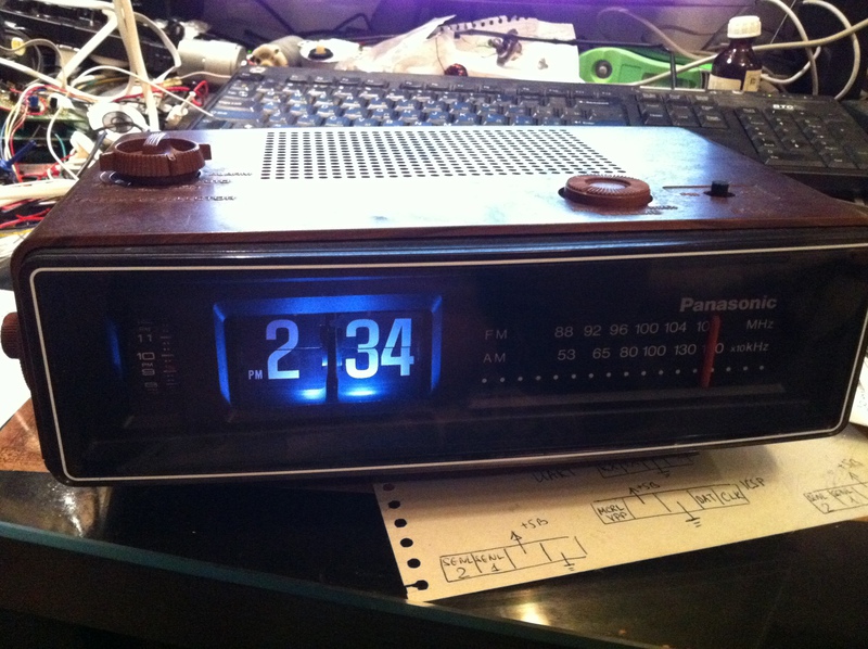
Unfortunately, miracles do not happen. The watch itself will have to be bought for real dollars. Here is an example of a lot on Ebay, somewhere for $ 35 I bought them. The model is either the same, or almost the same as in the film. According to some indications in the movie RC-6050, but I did not manage to quickly verify this, so I will not argue. We drove, it seems, for a long time. Three months.
')
Step Two
The clock is worth a tiny transformer 110V. Actually the fact that I returned to these hours three or four years later after I gave them to a friend, we owe a small party, during which we plugged the clock directly into the outlet without an adapter. The transformer immediately quietly died without smoke and noise. Information on the transformer could not be found, so I began to read tea leaves. The secondary winding was two-section, I reeled it, counting the turns. So I figured out the relationship of the turns in the sections of the secondary windings. Then I carefully looked at the engine, which almost directly feeds from one of the transformer windings and found on it, in addition to the factory sticker, a small sticker with the inscription 10VAC, which means 10 volts AC. We know the voltage on one of the windings, we know the ratio of turns, we find that on the second winding there is 6V.

Fortunately, on the balcony there was a transformer from a microwave, which, as a matter of luck, almost 10B and 14B were caught among a pile of secondary windings.
* The microwave transformer is not the three kilogram pig that feeds the magnetron, but the transformer from the electronics unit is quite decent sizes.
We connect and voila - everything works!
Step Three
All, yes, not all. It turns out that the axis with the flaps is driven by an AC motor, the speed of which depends on the frequency of the supply voltage. The clock, being stuck into our outlet, was lagging far behind (if we apply the proportion, we’ll find out that 72 seconds pass on this clock in our world in 72 seconds. It seems to me that scientists from CERN used the American equipment when they measured the neutrino speed the frequency of the ripple voltage did not think ... At least it looks more likely than that they did not take into account the slowdown of the clock on a moving satellite). So, the new challenge is to turn 10V 50Hz into 10V 60Hz.
* An inquisitive reader will ask - why not just go through the gearbox, so that at the previous engine speeds the clock shaft throws off the plate in exactly one minute? Or why not just change the engine? The answer is complex: the engine parameters are not fully known, there is no place to take the gears, my hands are not growing from the right place, and in general, why should I burn so much electronics? So that at the most crucial moment you can go crazy and take up a file with a hacksaw? Fig with two!
Well, what, you need to do a voltage converter. If you try to google, it turns out that this is a project for many, many nights and dollars. And I went for almost the whole day and thought - how would I get a sine (well, get a sinusoidal voltage), how to envelop it in S-PWM (this is Sine wave - PWM, i.e., pulse-width modulation with a variable period which being attached to the engine will give all the same sine). Moreover, the lasagna on the forums has formed a clear understanding that the sinns should be, if not perfect, then close to ideal with an error of no more than 0.01%, and otherwise harmonics, face beats and destruction of the engine, clock, apartment, and possibly the whole house with them. . It was really scary.
But after consulting with the guys at roboforum.ru , I was poking my nose into an article about the “modified sine” and decided to take the risk. In principle, then there are a lot of options - everything is limited only by your imagination. I took a homemade driver for testing, which, in fact, is an H-bridge. Who is not familiar with this miracle, you are welcome to read here . I connected ORduino Nano to it, wrote a simple program that did the following:
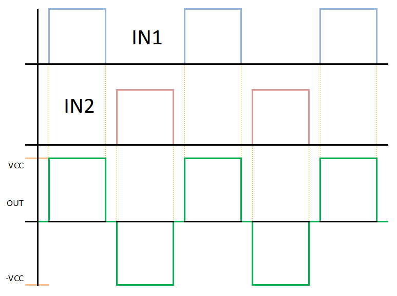
Those. generated almost a sine. Who does not see the green sine in the picture - try to look through anaglyph glasses or looking at one point behind the monitor plane, i.e. reducing eyes (joke).
With a sinking heart, I connected the output of the bridge to the engine and oh, a miracle! - the engine spun. Further transferred the idea to the "real" iron. I had a semi-burnt PIC16F887, and a chip l293d (four-half bridge). I assembled the following scheme on the breadboard:
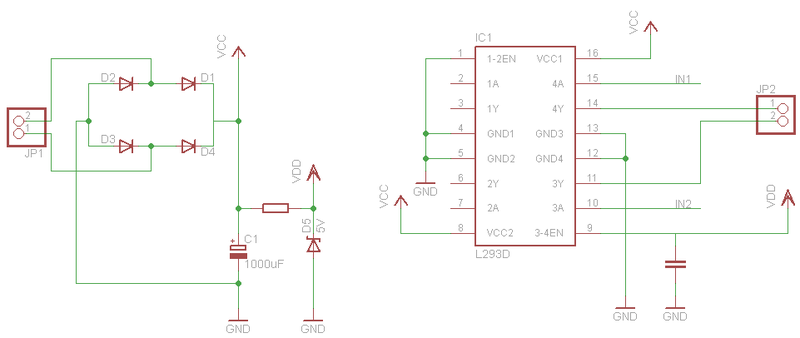
At the inputs IN1 and IN2, you can send a periodic signal from anything - a microcontroller, a circuit at 555, and anything else. The resistor for the Zener diode needs to be calculated for its circuit (maybe you don’t need a Zener diode resistor at all. But if you need it, look in Google for “calculating a parametric stabilizer.” I used a 470 Ohm resistor to power my poor guy).
I wrote the most complicated program for PIC already:
/*
* File: flip_clock_main.c
* Author: ImWode
*
* Created on 17 2011 ., 21:58
*/

#include "pic.h"

__CONFIG(INTIO & WDTEN & PWRTEN & MCLRDIS & BORDIS & LVPDIS & UNPROTECT);

void configure (void);

int i = 0;

int main(void) {

configure(); //

while (1)
{
CLRWDT(); //
}
}

void configure (void)
{
OSCCON = 0b01111111; //8,
ANSEL = 0x00;
ANSELH = 0x00;

TRISA = 0x00;

T2CON = 0b00000100; //
TMR2IF = 0;
TMR2IE = 1;
TMR2 = 0;

PEIE = 1;
GIE = 1;
}

void interrupt isr (void)
{
if (TMR2IE && TMR2IF) /-
{
switch (i++)
{
case 52:
RA3 = 0;
break;
case 64:
RA2 = 1;
break;
case 116:
RA2 = 0;
break;
case 129:
RA3 = 1;
i = 0;
break;
}
TMR2IF = 0;
}
}
Soldered everything in the clock and everything. The house is standing, the light is on, the clock is walking, the accuracy is acceptable (about a minute per day).
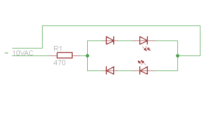
And, yes, I also made the backlight, as my own was burned. I did not find a 10VAC bulb, so I made it on two white LEDs:
Step Four (instead of the third for especially confused)
In fact, instead of a quasi-sine it is possible to make quite a decent sine with the same scheme. According to the plate, take the sine value and give the same input to the second input during the positive half period to one input of the bridge, and during the negative half period. Everything will look very decent, the main thing is to know what the chosen H-bridge is capable of (for example, l293d asks not to click it more often than 5 kHz, and at the same time it will warm up like a furnace. Carefully with this).
Well that's all
I'm sure today you will walk and hum all day: I got you babe!
Source: https://habr.com/ru/post/130785/
All Articles