Uneven hours

The idea of this watch is that the arrows on them move unevenly, then accelerating, then lagging behind, but nevertheless, on average, the clock shows the correct time. Now I will tell how to make such.
Autopsy
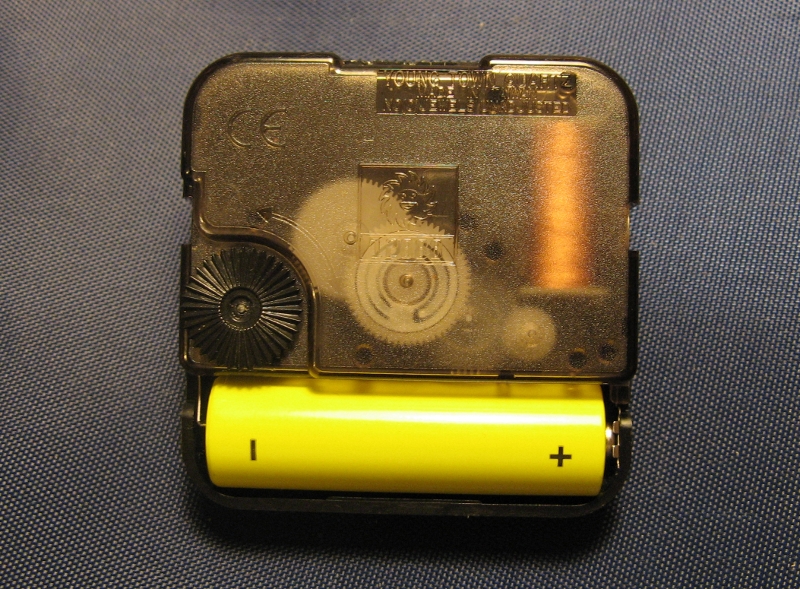
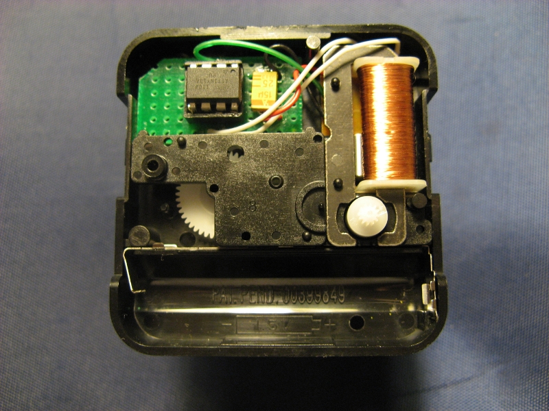
The basis is taken wall quartz analog clock. They can be decorated as you like, but in 99% of cases there is a standard Chinese mechanism with plastic parts inside. Here is this:
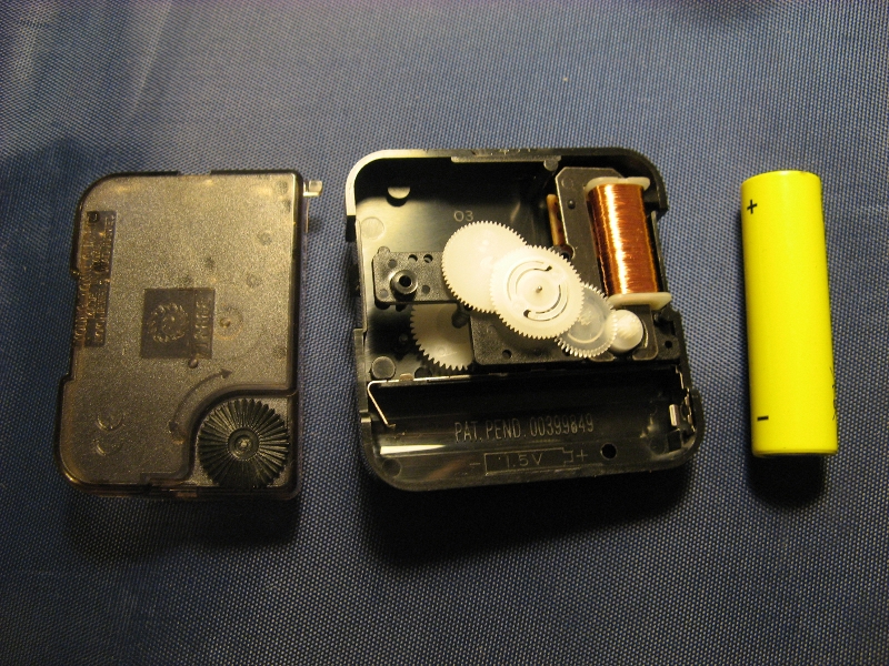
We open the case, simultaneously noting the availability of free space, which is very good for us.
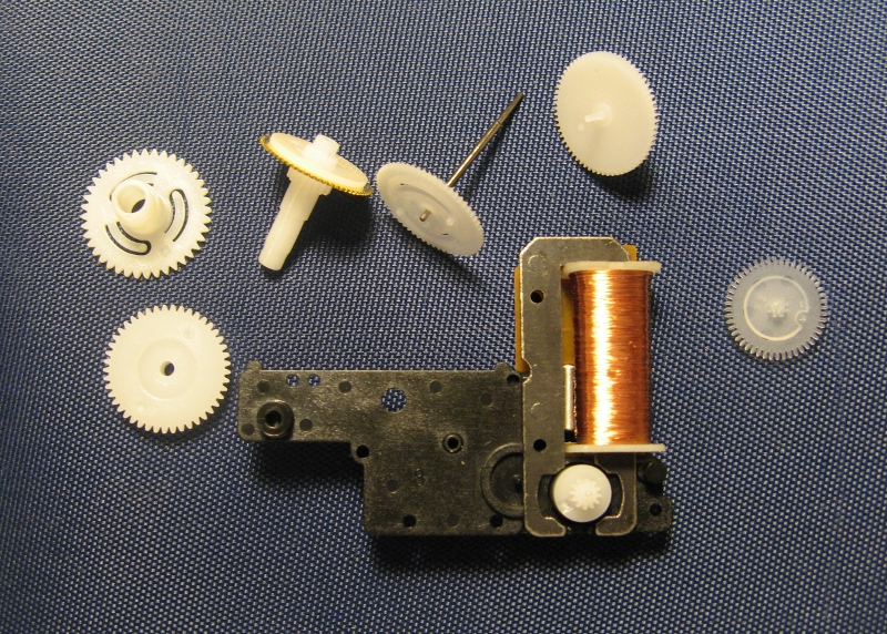
Carefully disassemble the mechanism, trying not to forget which gear where to put.
')
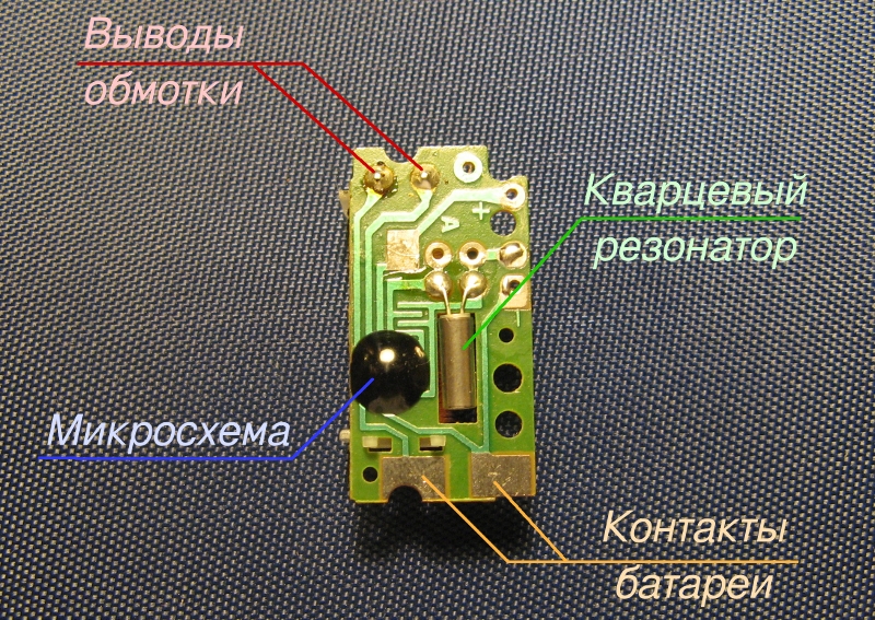
The clock is driven by a stepper motor, which consists of a stator with a winding and a rotor with a permanent magnet. Once a second, electric pulses are applied to the winding, and with each pulse the rotor rotates 180 °. Here is the engine in disassembled form:
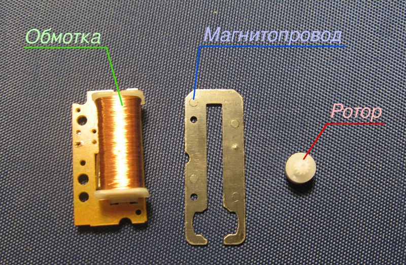
The clock of the generator is fixed on the reverse side of the winding. Here's what she looks like:
Brain transplant
The clockwork will be controlled by the ATtiny13A microcontroller, chosen mainly on the principle of “set what is”. An alternating polarity pulse with a duration of approximately 100 ms must be applied to the motor. Each pulse moves the second hand by one mark.
As you can see, everything is very simple: we connect the controller with two leads to the winding, supply power ... Stop! But after all, the clock is powered by one half-volt battery, and the minimum operating voltage for ATtiny13A is 1.8 volts. How to be? In fact, AVR controllers can operate at a supply voltage of 1 volt and even lower ( for example ), but under two conditions. First, the clock frequency should be low, in the region of tens of kilohertz. Secondly, clocking should be done from an external source.
Where to get external clock signal? The solution is obvious: from a regular clock generator. It generates a signal with a frequency of 32 768 Hz (2 15 Hz), which can be removed from one of the findings of quartz (from which - determined experimentally). We take our board and solder wires to it to remove power, a clock signal, and also to control the engine. It is also necessary to cut the tracks from the native generator to the winding terminals.

Wiring the microcontroller is as simple as two kopecks:
Just ask to pay attention to two points. First, at extra low supply voltage, the output keys of the ports do not open completely, therefore, to reduce the resistance, the terminals are paralleled in pairs ( PB0 with PB1 , and PB2 with PB4 ). Secondly, a tantalum capacitor should be placed in the power circuit, with a minimum leakage current.
The controller is mounted on the trimming of the breadboard and is perfectly located in the free space in the corner of the case:
Since it is not possible to reflash the MC directly in the circuit, I strongly advise you not to solder it intentionally, but install it in the socket.
Firmware
The logic of the clock is as follows: the intervals between the steps of the second hand have a random duration, but it must take a full turn in exactly one minute to avoid the accuracy of the stroke. Experimentally, it was found that the minimum interval between pulses is 1/4 of a second, an attempt to move the arrow faster leads to skipping steps. From this we will make a start, let the duration of each interval be a multiple of this minimum value. It will be convenient to divide a minute into 240 "ticks" of a quarter of a second each.
The main problem that arose while writing the firmware was how to randomly split a minute into 60 intervals. After spending a couple of hours and writing several sheets of paper, I made two algorithms. The first was to form an array of 240 elements in which the numbers of all the “ticks” were placed. Then, 59 elements were randomly selected from the array, each of which was the number of a “tick” on which the arrow would move. The second algorithm consisted in dividing the four-second interval (16 "ticks") randomly into two parts, each of which was then also divided in two. After performing these operations on 15 intervals, it turned out 60 values in the range from 1 to 13 "ticks", and the sum of all these values was exactly 240.
Unfortunately, neither the first nor the second algorithms I managed to implement on ATtiny13 due to the extremely small amount of memory of this MK (1 KB of FLASH and only 64 bytes of SRAM). Probably, some assembler guru could do it, but I acted easier and rigidly scored one interval duration table in the code. The fact that the rhythm of movement of the arrow will be repeated every minute should not immediately be evident.
The program is organized as follows. Each “tick” (1/4 second) timer generates an interrupt, during which the “tick” number is checked, and, if necessary, a voltage is applied to the motor winding, and the duration of the next interval is extracted from the table. After 100 ms, a second interrupt is generated, through which the voltage applied to the winding is turned off. The rest of the time, the controller is in sleep mode to reduce power consumption. The link to the full source code is given at the end of the article.
It is also necessary to flash the Fuse bits of the controller in order to enable the external clocking mode (values other than the factory ones are highlighted):
SELFPRGEN = 1
DWEN = 1
BODLEVEL1 = 1
BODLEVEL0 = 1
RSTDISBL = 1
SPIEN = 0
EESAVE = 1
WDTON = 1
CKDIV8 = 1
SUT1 = 1
SUT0 = 0
CKSEL1 = 0
CKSEL0 = 0
I hasten to note that after installing fusions in this way, the controller cannot be reflashed without an external clock source.
Assembly
So, the controller is programmed, installed on the board, which, in turn, is fixed in the case with a drop of glue. You can assemble the mechanism back, fix the arrows and enjoy the result:
Yes, my watch also goes in the opposite direction, which additionally dements the casual observer.
Links
- Firmware source code: http://pastebin.com/P3y6wBUh
- Similar project: Vetinari's Clock
- AVR operation at extra low voltage: Using an AVR as an RFID tag
Source: https://habr.com/ru/post/130594/
All Articles