Camera Angle Control
Formulation of the problem:
The advantage of a static video camera is that it allows you to continuously monitor the same, certain solid angle of the protected space.The advantage of the PTZ camera is that it allows you to control the solid angle of space, which can be remotely changed by the operator.
The price of a PTZ camera is significantly higher than the static one. Our task is to make our own PTZ camera at an affordable price.
Objective:
Development of algorithms and software and hardware to control the process of angular movement of a video camera based on a stepper motor without the use of high-precision mechanics and the technical implementation of this control system based on a personal computer.')
This goal is achieved by solving the following main tasks:
1. Analysis of the existing design features of stepper motors and their control methods.2. Development of algorithms and software and hardware for controlling the process of angular displacement (rotation) of a video camera using stepper motors.
3. Technical implementation of the control system of a stepper motor based on a personal computer (PC).
Scientific and practical significance of the work:
The developed algorithms and software and hardware for controlling the rotation of cameras using stepper motors will significantly increase the viewing angle of video surveillance systems based on the use of low-cost webcams that do not have high-precision mechanics to move them.Design features of stepper motors:
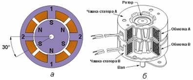
A stepper motor is an electromechanical device that converts a control signal into an angular (or linear) movement of the rotor with its fixation in a predetermined position without feedback devices. When designing specific systems, one has to make a choice between a servomotor and a stepper motor. When precise positioning and precise speed control are required, and the required torque and speed are within tolerance limits, the stepping motor is the most economical solution. Unlike collector engines, in which the electromechanical torque increases with increasing speed, a stepping motor has a higher torque at low speeds and a much lower maximum speed.The most common are permanent magnet motors, which consist of a stator having windings and a rotor containing permanent magnets. The alternating poles of the rotor have a rectilinear shape and are parallel to the axis of the engine.
Ways to control stepper motors:
The bipolar motor has one winding in each phase, which must be re-polarized by the driver to change the direction of the magnetic field. For this type of engine requires a bridge driver, or half bridge with bipolar power. In total, the bipolar engine has two windings and, accordingly, four outputs.The unipolar motor also has one winding in each phase, but there is a diversion from the middle of the winding. This allows you to change the direction of the magnetic field created by the winding, by simply switching the winding halves. This significantly simplifies the driver circuit, which should have only 4 simple keys. The middle winding leads can be combined inside the motor, so this motor can have 5 or 6 leads. Sometimes unipolar engines have 4 separate windings, so there will be 8 total pins. With the appropriate connection of the windings, such an engine can be used as unipolar or bipolar.
The most effective way to control a stepper motor is the half-step mode, i.e. half step mode, when the engine takes a step in half the main. For each second step, only one phase is powered, and in other cases, two are powered. As a result, the angular displacement of the rotor is half the angle of the main step, however, the half-step mode usually does not allow to get the full moment.

Hardware implementation of stepper motor control using a PC:
Based on the analysis, a stepper motor SD-1EM was selected, which has the following features: the number of steps per revolution is 200, the maximum winding current is 500 mA, the nominal power is 12 W.As an engine driver, it is advisable to use the ULN2003A chip. This is a set of transistors assembled according to the Darlington circuit with an open collector and a protective diode in the load circuit. The microcircuit contains 7 switching channels with a load current up to 500 mA.
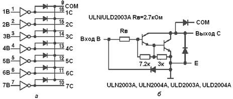
The chip has resistors in the base circuit that allows you to directly connect its inputs to conventional digital circuits. All emitters are connected together and brought to a separate conclusion. The outputs of the transistor switches are protective diodes, which allows you to manage with this chip inductive loads with a minimum of external components.

The COM signal (pin 9) is connected to the power supply not directly, but through a zener diode. This is done in order to protect the circuit from the voltage of the EMF of self-induction arising in the coils when turning off the supply voltage of the circuit. The driver chip is controlled by the parallel LPT port of the personal computer in the ECP / EPP mode using the lower four data lines (D0-D3).
Features of stepper motor control algorithms:
For a half-step motor control, it is necessary to install a voltage of + 5V on the D0, D1, D2, D3 LPT pins of the PC port in accordance with the scheme, which corresponds to supplying them with logical units in a certain sequence determining the direction of engine rotation.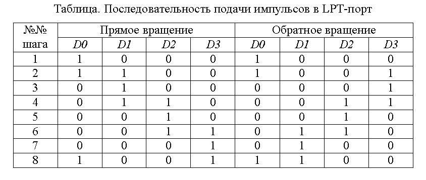
Signals are given at certain time intervals, which are programmed using the program flow stop function (SLEEP) and depend on the time during which the rotation command must be processed.
Software implementation:
The Delphi environment is used as a programming language, since it has a simple syntax, successfully demonstrates the paradigms of procedural programming and OOP, and also has a simple and understandable architecture of standard libraries.To work with the LPT communication port running under the Microsoft Windows operating system, two WinAPI functions are used - Inp32 and Out32, which are part of the standard inpout32.dll library.
A listing of the subroutine that provides the direct angular displacement of the Alpha motor during T, starting from the initial position of the shaft St, is shown below.
procedure Forward(Alpha:Real, T:Real, K:Real, var St:Integer);
const PORT=888;
const Steps:array[1..8] of Byte = (1, 3, 2, 6, 4, 12, 8, 9);
var I, DT:Integer;
begin
DT:=Round(T/(Alpha*K));
I:=0;
while (I<Trunc(Alpha*K)) do begin
Out32(PORT, Steps[St]); sleep(DT);
St:=St+1;
If (St>8) then St:=8;
I:=I+1;
end;
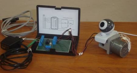
end;Conclusion:
On the basis of the developments, a technical implementation of the ShD-1EM stepper motor control system based on a personal computer was implemented to control the angular movement of a Logitech QuickCam webcam with the following characteristics: video capture in real time at up to 30 frames per second with a resolution of 640x480 pixels.Bibliography:
1. Damyanovski V. CCTV Bible security television. Digital and network technologies ". Is-es-Press, 2006. - 480.
2. Dubrovsky I.L., Dambrauskas A.P., Rybin A.A. Microprocessor control of industrial robots electric drives: a tutorial /; - Krasnoyarsk, KSTU, 1993 - 88s.
3. Kenio Takashi. Stepper motors and their microprocessor control systems: Trans. from English., M .: Energoatomizdat, 1987 - 199s.
4. Lebedev N.I., Gundshu V.M., Yavdoshak Ya.I. Valve electrical machines. Spb .: Science, 1996. - 352s.
5. Stepper motors. Motor reducers: portal [Electronic resource]. - Access Mode: stepmotor.ru
PS The project was implemented and described in December 2008 as part of school work contests. The first time the article was published in the sandbox. After that, copies began to appear on the network. From the second time it was published .
Source: https://habr.com/ru/post/130384/
All Articles