Simple binary clock with alarm clock on Arduino

After reading interesting articles about how people invent and implement useful and just fun projects on the Arduino platform, I also wanted to make a simple, interesting and at the same time bringing at least some useful design.
But I had to come up with something not very complicated, since I still had no experience, no more serious electronics like sensors and motors, or expansion cards. Therefore, after a day of meditation, I decided to look for inspiration on the Internet. Not long wandering around the expanses of the network, I found in one bourgeois blog the implementation of a binary clock. That was what was needed, no complicated electronics, for a start it was the most.
')
But I immediately decided that in the end I would do the whole construction not on the breadboard, but at least on the breadboard board so that I would not have to disassemble everything and the efforts would be wasted. So I had to arm myself with a soldering iron and everything that came with it.
The first steps
The Arduino board is the easiest to buy, but why waste time again if you can make it manually. Therefore, I asked the person for whom this is nothing, to help me. The benefit of instructions and examples on the Internet abound.
And after a couple of days I had a handkerchief.
You still need breadboard and wires for the connection, so they had to be ordered. Delivery did not take much time.
Also, small things, in the form of resistors, LEDs, buttons, piezo-diggers and what can be found by disassembling an old modem or a CD-ROM drive. I still had stocks of old Soviet radio components.
For starters, this is more than enough. Now you can start to train, to start blinking with LEDs, to figure out how to work with analog connectors and with PWM.
Return to the original idea. Training
Having dealt with the basic principles of the arduino and the development environment, we return to the idea of making a binary clock. Only I already wanted a little more, not just making the display of hours and minutes, but also add at least a simple alarm clock.
Thus, for all this we need:
- arduino;
- breadboard (not necessary, you can immediately solder everything on the breadboard);
- wires For jumpers, I generally used from a twisted pair, they are copper there, they are remarkably soldered, and for connecting to arduino from the cases of the old system managers, since I have pins on self-made arduino, not connectors, unlike factory ones;
- 13 LEDs;
- 4 buttons (one with fixation);
- 14 220 ohm resistors, 360 ohms possible (for LEDs and tweeters);
- 4 resistors of approximately 2.2 kΩ each (for buttons);
- piezopischalka.
How will they work
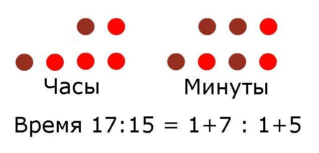
To indicate hours and minutes, two rows of LEDs are used, one for the first digit, the other for the second, adding which we get the desired value. From the picture all at once should be clear.
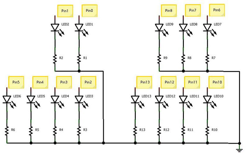
Scheme
The LEDs are connected very simply, but they must be stuck through resistors, one foot to the ground, the other in the arduino, to pins from 0 to 8 and from 10 to 13. The resistor can be connected from the side of the ground, at least from the side of the board.
Everything is as in the following diagram, all conclusions are painted.
To connect the tweeter just left a free 9 pin, since we need a pin supporting PWM. I hooked the resistor to the squeaker to 220 ohms, but it can be smaller, it will squeal louder. What is PWM can be read here .

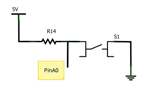
Since my type of arduino no longer has free digital pins (if you buy an Arduino Mega, then there are still a lot of them), you will have to use analog buttons for buttons. We output one output to the ground, the other through a resistor to the arduino. The difference in connection to the analog pins is that we will not read the HIGH or LOW digital signal, but the input voltage level converted to an integer value. Therefore, to determine whether the button is pressed or not, it is necessary to check the value from the ADC. They will take analog pins from 0 to 3.
Two buttons to set the minutes and hours. One to switch modes. And one more, which is with fixation, for turning on / off the LED backlight.
The scheme of switching on the button is as follows, for the others it is similar.
General form:
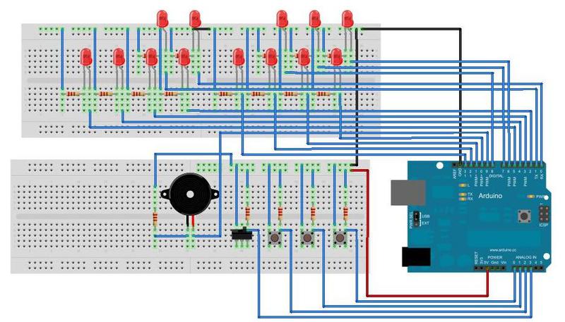
It can be easily assembled on the breadboard. But I want the same finished device, albeit connected to the arduino.
Let's figure out how it will work and look
Therefore, at first, all the same, we sketch our sketch, in which for now we’ll make the switching of the minutes, and collect all this on the breadboard, for verification.
Collected, hooked:
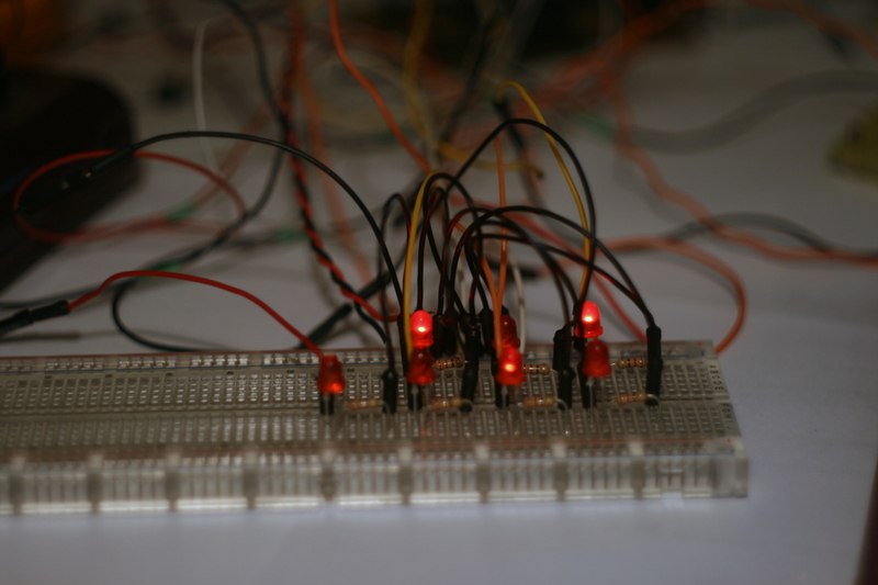
Works. Fine.
Now let's see how it will look already on the board.

It looks again not bad, still a lot of free space for buttons and tweeters.
We will solder
First of all, you need to check out what worked for us on the breadboard.

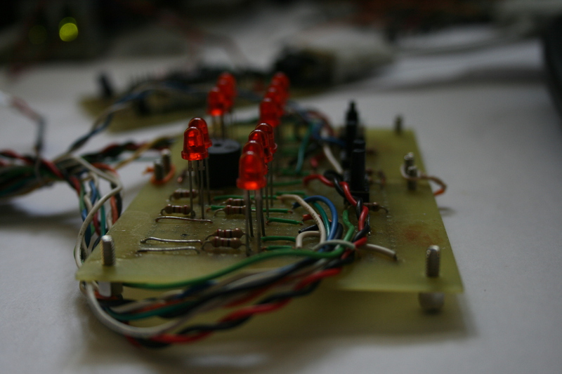
And making sure that I am still capable of something, in terms of soldering and not burning, you can continue.
The result is the following design, which, although it looks quite clumsy, but works quite stably.
Code
After the board is ready, you can continue to write code. As I have already said, it was not difficult to find a similar one, therefore, taking other people's work as a basis, you can do it the way you like most.
The purpose of the buttons is explained in the following picture, of course, one could also add control elements and unload these, but on the contrary I did not want to turn back a bunch of them, so I did so.

The sketch turned out quite simple, albeit voluminous. I don’t see the point of giving the implementation of the subroutines, since everything is very clear and understandable from the code (and comments in it), which can be viewed at this link . Since this is my first development experience for arduino, I am sure that it could be done better. So I will be glad to hear the advice.
Conclusion
Overall, I am very pleased. I will continue to explore the arduino platform.
Video implementation:
Thanks for attention!
Links
Homemade Arduino - robocraft.ru/blog/arduino/19.html
What is PWM - arduino.ru/Tutorial/PWM
Sources - github.com/proshik/binary_clock
Source: https://habr.com/ru/post/130227/
All Articles