Color music based on FPGA
Color music or the development of a three-band real-time spectrum analyzer using FPGA-based wavelet analysis.
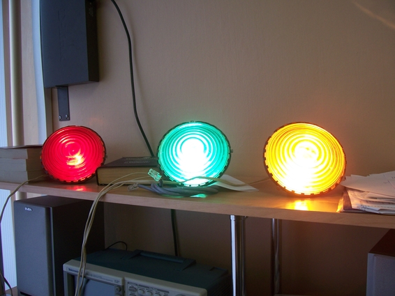
One day my dad showed me the analog color music he had created. The three spotlights blinked cheerfully to the music, each was tuned to its own frequency range, and the fourth spotlight came on only when one of the spotlights went out so that the room was not dark in the lull. Then something broke in her, and she lay gathering dust for a dozen years on the shelf. Since I really love listening to music, and I still have vivid memories of color music, I really wanted to resurrect it and enjoy the flashing of spotlights to my favorite rhythms. Well and, of course, to use high technologies for the realization of our plans ...
Since I work in a company engaged in processing digital and analog signals based on FPGA, the idea arose by itself. I decided to create a “digital hammer” that would drive the audio signal in real time through three filters tuned to three frequency bands. Searching on the Internet which frequency bands are used in creating color music (for this theme is rather old), I found the following:
LF: 40 - 110 Hz
SC: 1000 - 5000 Hz
HF: 10,000 - 18,000 Hz
As filters, I studied the wavelet transform, which the company is engaged in, and I received three sets of coefficients with which I convolved data from an ADC with a sampling frequency of 3 MHz. AFC filters are shown in the figure:
')

The scheme of the resulting project is as follows:
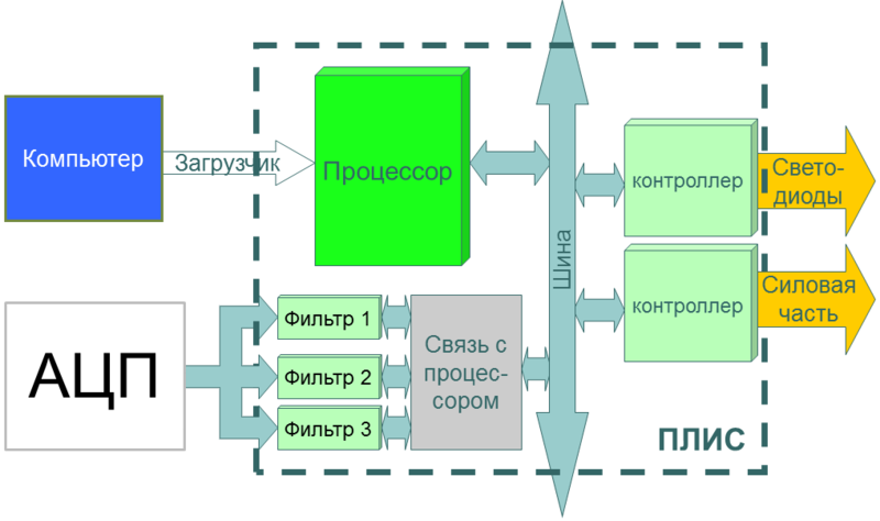
As a processor, I used a Forth-processor created by the same company, so I am perfectly able to work with it. In the hardware, memory blocks with filter coefficients were created, a data reading unit with an ADC, a convolution of ADC data and filter coefficients, as well as a PWM block for LEDs. The whole thing was connected to the processor, compiled, and wired into the Spartan-3 XC3S400.
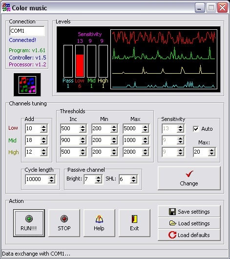
Then I began to write a program for the processor that would deal with the purpose I needed - read the results of the convolution (the amplitude of the signal at certain frequencies) and give the resulting values to the PWM LEDs. The results of the convolution were correct, but for some reason the LEDs were constantly burning and fading only when the music almost subsided. I began to understand and realized that the brightness of the LED depends on the PWM threshold not linearly, but logarithmically. That is, if I have 1024-bit PWM, then in order to smoothly change the LED brightness from the dimmest to the brightest, I had to consistently take such numbers of the PWM threshold: 0, 15, 31, 63, 127, 255, 511, 1023. Thus I got 8 different degrees of LED illumination, and that was enough for me. And after adjusting the results of the convolution to these threshold numbers, the color music worked as I wanted. Next, I wrote the logic of the passive channel. Its approximate work is such that when any of the channels dies out, this passive LED starts to gain brightness. Thus, the room will never be completely dark. I wrote the same auto-sensitivity control - when the music volume is changed, the program itself increases or decreases the coefficient, which is multiplied by the result of the convolution from the filters. I also wrote a Delphi program that communicates with the board via the RS-232 COM-port and can build graphs on all channels in real time, and also change the values of some internal variables as fine-tuning. All these settings can be recorded on the EEPROM 93C86 flash drive, which was soldered on the board issued to me. Appearance of the program:
When it all worked, it was necessary to create a power unit. As a transition to the power section, I used optothyristors T0125-12,5:
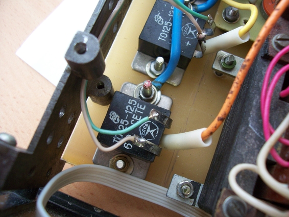
These elements have 4 outputs: 2 of them are a normal LED, and the other two are a power switch. You can guess that when the LED is on, then the two power leads close, and vice versa. I duplicated the PWM channels in the hardware of my project and connected them to the conclusions of optothyristors (though I had to invert PWM for these channels due to the reverse logic of the optothyristors), spread out a small kerchief for the power unit to connect searchlights.
Everything worked the first time, and it still works. As spotlights used conventional bulbs 220V.

Subsequently, I decided to add two analog meters to the color music panel for two channels, made them a beautiful green backlight and the result was such a box:

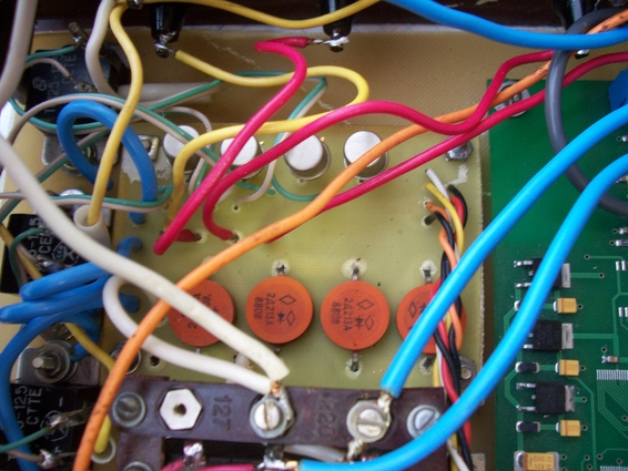
But inside it all looks like this:

You can watch the video of the work of color music, but note that everything flashes much less often than it actually is.
The firmware file for Spartan-3 XC3S400-4tq144 as well as the Delphi program with the sources here . Printed circuit boards lay out a little later. This kit is enough for those who seriously want to build themselves the same system. =)
Source: https://habr.com/ru/post/130154/
All Articles