Text VGA module on VHDL
In this article I will introduce a text VGA module written in VHDL. This module can be useful when debugging a board, and takes up relatively little space.
The module operates at a clock frequency of 50 MHz.
Produces a picture with a resolution of 640x480 with a frequency of 60Hz.
The character size is 8x16 dots. On the screen 8025 characters.
The palette is 32 colors.
Resources occupied in FPGA:

')
The module interface includes a clock generator input (clk), an output to the VGA connector (r, g, b, vsync, hsync) and an output to the processor bus (addr, data, iowr, dout). On the board with which I worked, there are 8-bit DACs in the amount of three pieces (one for each color), so 8-bit lines of colors come from the module. Taking the most significant bit of color, we get a working version for boards without a DAC.

The monitor requires 3 synchronization signals and 3 color signals. To generate synchronization signals, VCounter and HCounter counters are used. Synchronization signals are issued at the moments shown in the diagram.

Counter code:
Formation of synchronization signals:
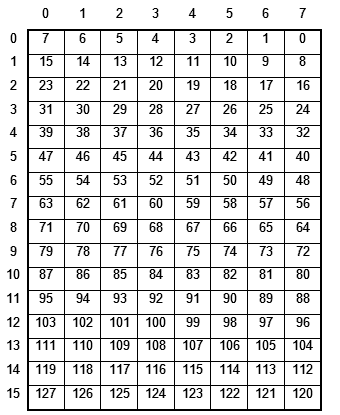
The size of one character is 8x16 dots. The array of characters will be 256 cells of 128 bits each. Each bit is responsible for whether there is a point in the current position or not. The location of the points in the memory cell:
In FPGA there is a block memory configuration of 1024x18 bits (18432 bits), which we will be guided by. CAD automatically implements almost any selected configuration using such memory blocks. So, for the memory of symbols, 256 × 128 bits = 32768 bits of memory are needed, which will take 2 memory blocks (BRAM).
The symbol memory is initialized during design and can be changed during operation.
Another necessary memory is the screen (visible area) memory. In this memory, we encode the symbol number, symbol color and background color. To save color memory encode number in the palette. Based on the configuration of the memory with a cell of 18 bits, we will take the symbol number to 8 bits, the color of the symbol is 5 bits, and the background color will also be 5 bits. Under the palette allocated 32 cells of 24 bits (8 bits per color).

Based on the resolution and size of the character, the screen fits 80x30 characters. But it takes 2400 cells in memory (3 memory blocks). Since, from the very beginning, the task of the minimum size of this module was posed, 5 bottom lines were cut out. As a result, we get 80x25 displayed characters, which takes 2000 memory cells (2 memory blocks).
Symbols are generated in the coregenerator. The memory is connected to the module as follows:
Screen memory is created by writing template code (although you can do the same as with character memory).
You also need to set the color table of the palette, which is carried out as follows.
All the necessary memory is formed, now you can do the implementation of the preparation of the pixel for display on the screen.
Current FPGA design trends imply fully synchronous designs. We will not deviate from these trends, and will implement to prepare the next pixel pipeline. At the entrance there will be counters HCount and VCount, which determine the current position on the screen, and at the output - the color of the pixel that needs to be output.
Stages conveyor:
We will work with the module via the bus with the interface
The bus is controlled by a fort processor, implemented on the same FPGA. At the OUTPORT command, the Addr lines are set, Data and the Iowr line rises to “1” for one clock cycle. At the INPORT command, the processor exposes the Addr line and retrieves data from the Dout line.
Bus operation example:
In the same way, most of the commands for working with the module are implemented.
Full listing of the module is available here.
Module listing
To initialize character memory
UPD:
Basic functions
300 - write / read from screen memory
301 - address to write to the screen memory
302 - set the X coordinate of the carriage (GotoX)
303 - Set the carriage coordinate (gotoY)
304 - set the color of the symbol (SetColor)
305 - set the background color (SetBgColor)
306 - character output and carriage movement (EMIT)
307 - mode switching
1 - LowLevel mode. Functions 300, 301 available for direct memory handling
0 - Normal mode. Function 306 is available to set the character with the specified color to the specified position and move the carriage.
308 - CR
309 - VGA_SetData (A ++)
Cursor options
310 - set the cursor parameters.
0 bit - the bottom bar in the cursor
1 bit - black square
2 bits - flicker
3 bits - vertical strip
311 - setting bit №0 in the cursor parameters
...
314 - setting bit number 3 in the parameters of the cursor
320 - setting the cursor color
321 - setting the blink time of the cursor
322 - setting the time of the burning cursor
Work with palette
330 - Setting the address of the color palette
331 - Record color to set address
Working with symbol table
335 - Setting the address in the symbol table
337 - Write NewSymbol at a given address
340 - Setting the low 32 bits of the NewSymbol signal (NewSymbol (31: 0))
341 - Setting the next 32 bits of NewSymbol (63:32)
342 - NewSymbol (95:64)
343 - NewSymbol (127: 96)
Thanks for attention.
General characteristics
The module operates at a clock frequency of 50 MHz.
Produces a picture with a resolution of 640x480 with a frequency of 60Hz.
The character size is 8x16 dots. On the screen 8025 characters.
The palette is 32 colors.
Resources occupied in FPGA:
')
Implementation
The module interface includes a clock generator input (clk), an output to the VGA connector (r, g, b, vsync, hsync) and an output to the processor bus (addr, data, iowr, dout). On the board with which I worked, there are 8-bit DACs in the amount of three pieces (one for each color), so 8-bit lines of colors come from the module. Taking the most significant bit of color, we get a working version for boards without a DAC.
entity vga_text is
Port ( clk : in STD_LOGIC ;
iowr : in STD_LOGIC ;
addr : in STD_LOGIC_VECTOR ( 31 downto 0 ) ;
data : in STD_LOGIC_VECTOR ( 31 downto 0 ) ;
dout : out std_logic_vector ( 31 downto 0 ) ;
r : out STD_LOGIC_VECTOR ( 7 downto 0 ) ;
g : out STD_LOGIC_VECTOR ( 7 downto 0 ) ;
b : out STD_LOGIC_VECTOR ( 7 downto 0 ) ;
vga_blank : out STD_LOGIC ;
vsync : out STD_LOGIC ;
hsync : out STD_LOGIC ) ;
end vga_text ;
The monitor requires 3 synchronization signals and 3 color signals. To generate synchronization signals, VCounter and HCounter counters are used. Synchronization signals are issued at the moments shown in the diagram.
Counter code:
architecture Behavioral of vga_text is
signal VCounter : integer range 0 to 520 : = 0 ;
signal HCounter : integer range 0 to 800 : = 0 ;
signal div : std_logic : = ' 0 ' ;
begin
process ( clk )
begin
if rising_edge ( clk ) then
div <= not ( div ) ;
if div = ' 1 ' then
if HCounter = 799 then
HCounter <= 0 ;
if VCounter = 520 then
VCounter <= 0 ;
else
VCounter <= VCounter + 1 ;
end if ;
else
HCounter <= HCounter + 1 ;
end if ;
end if ;
end if ;
end process ;
end behavioral ;
Formation of synchronization signals:
vsync <= ' 0 ' when VCounter < 2 else ' 1 ' ;
hsync <= ' 0 ' when HCounter < 96 else ' 1 ' ;
vga_blank <= ' 1 ' when ( ( HCounter > 143 ) and ( HCounter < 784 ) and
( VCounter > 30 ) and ( VCounter < 511 ) ) else ' 0 ' ;
The size of one character is 8x16 dots. The array of characters will be 256 cells of 128 bits each. Each bit is responsible for whether there is a point in the current position or not. The location of the points in the memory cell:
In FPGA there is a block memory configuration of 1024x18 bits (18432 bits), which we will be guided by. CAD automatically implements almost any selected configuration using such memory blocks. So, for the memory of symbols, 256 × 128 bits = 32768 bits of memory are needed, which will take 2 memory blocks (BRAM).
The symbol memory is initialized during design and can be changed during operation.
Another necessary memory is the screen (visible area) memory. In this memory, we encode the symbol number, symbol color and background color. To save color memory encode number in the palette. Based on the configuration of the memory with a cell of 18 bits, we will take the symbol number to 8 bits, the color of the symbol is 5 bits, and the background color will also be 5 bits. Under the palette allocated 32 cells of 24 bits (8 bits per color).
Based on the resolution and size of the character, the screen fits 80x30 characters. But it takes 2400 cells in memory (3 memory blocks). Since, from the very beginning, the task of the minimum size of this module was posed, 5 bottom lines were cut out. As a result, we get 80x25 displayed characters, which takes 2000 memory cells (2 memory blocks).
Symbols are generated in the coregenerator. The memory is connected to the module as follows:
signal SAddrA : std_logic_vector ( 7 downto 0 ) ;
signal SAddrRead, SAddrWrite : integer range 0 to 255 ;
signal SDataA, SDinA : std_logic_vector ( 127 downto 0 ) ;
signal SWeA : std_logic ;
- ...
component vga640_symbols
port (
addr : IN std_logic_VECTOR ( 7 downto 0 ) ;
clk : IN std_logic ;
din : IN std_logic_VECTOR ( 127 downto 0 ) ;
dout : OUT std_logic_VECTOR ( 127 downto 0 ) ;
we : IN std_logic ) ;
end component ;
- ...
begin
- ...
vga640_symbols_0 : vga640_symbols
Port map (
addr => SAddrA,
clk => clk,
din => NewSymbol,
dout => SDataA,
we => SWeA
) ;
SWeA <= ' 1 ' when ( isLowLevel = ' 1 ' ) and ( conv_integer ( addr ) = 337 and iowr = ' 1 ' ) else ' 0 ' ;
SAddrA <= conv_std_logic_vector ( SAddrWrite, 8 ) when ( isLowLevel = ' 1 ' ) and ( conv_integer ( addr ) = 337 and iowr = ' 1 ' ) else conv_std_logic_vector ( SAddrRead, 8 ) ;
Screen memory is created by writing template code (although you can do the same as with character memory).
type TScreen is array ( 0 to 1999 ) of std_logic_vector ( 17 downto 0 ) ;
signal Screen : TScreen ;
signal scrAddrA, scrAddrB : integer range 0 to 1999 ;
signal scrDataA, scrDataB, scrDinB : std_logic_vector ( 17 downto 0 ) ;
signal scrWeB : std_logic ;
- ...
begin
- ...
process ( clk )
begin
if rising_edge ( clk ) then
if scrWeB = ' 1 ' then
Screen ( scrAddrB ) <= scrDinB ;
end if ;
scrDataA <= Screen ( scrAddrA ) ;
scrDataB <= Screen ( scrAddrB ) ;
end if ;
end process ;
scrDinB <= scrDinBLowLevel when isLowLevel = ' 1 ' else scrDinBNormal ;
scrWeb <= scrWeBLowLevel when isLowLevel = ' 1 ' else scrWebNormal ;
scrAddrB <= scrAddrBLowLevel when isLowLevel = ' 1 ' else scrAddrBNormal ;
scrDinBLowLevel <= data ( 17 downto 0 ) ;
scrWeBLowLevel <= ' 1 ' when ( conv_integer ( addr ) = 300 or conv_integer ( addr ) = 309 ) and iowr = ' 1 ' else ' 0 ' ;
scrAddrBNormal <= GotoY * 80 + GotoX ;
scrDiNBNormal <= BgColor & Color & data ( 7 downto 0 ) ;
scrWebNormal <= ' 1 ' when conv_integer ( addr ) = 306 and iowr = ' 1 ' else ' 0 ' ;
You also need to set the color table of the palette, which is carried out as follows.
type TColor is array ( 0 to 31 ) of std_logic_vector ( 23 downto 0 ) ;
signal PalleteColor : TColor : =
(
0 => x "000000" ,
1 => x "0000FF" ,
2 => x "00FF00" ,
3 => x "00FFFF" ,
4 => x "FF0000" ,
5 => x "FF00FF" ,
6 => x "FFFF00" ,
7 => x "FFFFFF" ,
others => x "FFFFFF"
) ;
signal PalleteAddr : integer range 0 to 31 ;
All the necessary memory is formed, now you can do the implementation of the preparation of the pixel for display on the screen.
Current FPGA design trends imply fully synchronous designs. We will not deviate from these trends, and will implement to prepare the next pixel pipeline. At the entrance there will be counters HCount and VCount, which determine the current position on the screen, and at the output - the color of the pixel that needs to be output.
Stages conveyor:
- Calculation of signals scrX, scrY, determining the position in the visible part of the screen.
- Calculation of the signals defining the cell in the memory of the screen with the required symbol
textX = scrX / 8
textY = scrY / 16
Calculation of the signals that determine the desired pixel in the symbol
SymbolX = scrX mod 8 - 1
SymbolY = scrY mod 16
where mod is the remainder of the division. - Calculation of addresses on signals X, Y.
- Getting the current character.
- Getting the current pixel and the formation of color.
process ( clk )
begin
if rising_edge ( clk ) then
if div = ' 1 ' then
-- one
scrX <= conv_std_logic_vector ( HCounter - 139 , 10 ) ;
scrY <= conv_std_logic_vector ( VCounter - 70 , 10 ) ;
- 2
textX <= conv_integer ( scrX ( 9 downto 3 ) ) ;
textY <= conv_integer ( scrY ( 9 downto 4 ) ) ;
SymbolX <= scrX ( 2 downto 0 ) - 1 ;
SymbolY <= scrY ( 3 downto 0 ) ;
- 3
scrAddrA <= textY * 80 + textX ;
SymbolPoint <= conv_integer ( SymbolY ) * 8 + 7 - conv_integer ( SymbolX ) ;
-- four
SAddrRead <= conv_integer ( scrDataA ( 7 downto 0 ) ) ;
scrData <= scrDataA ;
-- five
if ( VCounter > 69 ) and ( VCounter < 470 ) then
if SDataA ( SymbolPoint ) = ' 1 ' then
curColor <= PalleteColor ( conv_integer ( scrData ( 12 downto 8 ) ) ) ;
else
curColor <= PalleteColor ( conv_integer ( scrData ( 17 downto 13 ) ) ) ;
end if ;
else
curColor <= x "000000" ;
end if ;
end if ;
end if ;
end process ;
b <= curColor ( 23 downto 16 ) when ( vga_blank = ' 1 ' ) else "00000000" ;
g <= curColor ( 15 downto 8 ) when ( vga_blank = ' 1 ' ) else "00000000" ;
r <= curColor ( 7 downto 0 ) when ( vga_blank = ' 1 ' ) else "00000000" ;
We will work with the module via the bus with the interface
- Addr (32 bit) - address
- Data (32 bit) - data
- Iowr (1 bit) - write (OUTPORT)
- Dout (32 bit) - response data (INPORT)
The bus is controlled by a fort processor, implemented on the same FPGA. At the OUTPORT command, the Addr lines are set, Data and the Iowr line rises to “1” for one clock cycle. At the INPORT command, the processor exposes the Addr line and retrieves data from the Dout line.
Bus operation example:
process ( clk )
begin
if rising_edge ( clk ) then
- setting the cursor to position X (GOTOX)
if conv_integer ( addr ) = 302 and iowr = ' 1 ' then
if conv_integer ( data ) > 79 then
GotoX <= 0 ;
else
GotoX <= conv_integer ( data ) ;
end if ;
end if ;
- set the cursor to the Y position (GOTOY)
if conv_integer ( addr ) = 303 and iowr = ' 1 ' then
if conv_integer ( data ) > 24 then
GotoY <= 0 ;
else
GotoY <= conv_integer ( data ) ;
end if ;
end if ;
end if ;
end process ;
In the same way, most of the commands for working with the module are implemented.
Full listing of the module is available here.
Module listing
To initialize character memory
UPD:
Basic functions
300 - write / read from screen memory
301 - address to write to the screen memory
302 - set the X coordinate of the carriage (GotoX)
303 - Set the carriage coordinate (gotoY)
304 - set the color of the symbol (SetColor)
305 - set the background color (SetBgColor)
306 - character output and carriage movement (EMIT)
307 - mode switching
1 - LowLevel mode. Functions 300, 301 available for direct memory handling
0 - Normal mode. Function 306 is available to set the character with the specified color to the specified position and move the carriage.
308 - CR
309 - VGA_SetData (A ++)
Cursor options
310 - set the cursor parameters.
0 bit - the bottom bar in the cursor
1 bit - black square
2 bits - flicker
3 bits - vertical strip
311 - setting bit №0 in the cursor parameters
...
314 - setting bit number 3 in the parameters of the cursor
320 - setting the cursor color
321 - setting the blink time of the cursor
322 - setting the time of the burning cursor
Work with palette
330 - Setting the address of the color palette
331 - Record color to set address
Working with symbol table
335 - Setting the address in the symbol table
337 - Write NewSymbol at a given address
340 - Setting the low 32 bits of the NewSymbol signal (NewSymbol (31: 0))
341 - Setting the next 32 bits of NewSymbol (63:32)
342 - NewSymbol (95:64)
343 - NewSymbol (127: 96)
Thanks for attention.
Source: https://habr.com/ru/post/129746/
All Articles