Ringed networks, or why do we need STP
The essence of the problem
The purpose of the switch network life (also known as a switch) is the relentless forwarding of packets from the sender to the recipient. To optimize the operation, the switch contains a so-called. A CAM table containing the addresses of the devices from which he once received packets, and the numbers of the physical ports from which these same packets were received.
In other words, if the switch recently received a packet from computer A on port 1, then the “comp. A ”->“ port 1 ”, and further packets addressed to computer A, are automatically forwarded only to port 1, and nowhere else, which saves network bandwidth and makes passive traffic interceptors ineffective.
But what should a switch do if a broadcast packet arrives?
It is logical to assume that such packets are sent to all ports, in addition, from where they were originally received .
That, with a certain network configuration, can lead to very sad consequences ...
Suppose several switches are connected in such a way that closed loops form in the system.
')
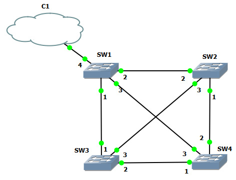
What happens if the broadcast packet comes to switch 1 from the cloud? He will propagate it and transmit to ports 1, 2 and 3 (the packet came from port 4, so it will not be sent back to it). Switch 2, having received a packet on port 2, will send copies of it to ports 1 and 3. Switch 3, if it receives a packet on port 1, will send copies of it to ports 2 and 3. Switch 4, after receiving a packet on port 3, will send copies to ports 1 and 2. After that, each copy, being transferred from the device to the device, will be multiplied according to the same scheme more and more until they totally occupy all the available bandwidth (or do not clog the brains of the devices until they lose their functionality).
But, at the same time, it’s impossible to do completely without “loops” in the network, since fault tolerance is the most important feature of a good network. That is, between any two important nodes of the network (I do not take into account the computer of an ordinary user) there should be more than one physical path in case a channel or an intermediate device fails. And that means loops.
STP to the rescue
The problem of the above-described “broadcast storms” is solved by the launch of the STP protocol (or one of its extensions) on the switches.
The Spanning Tree Protocol, or the protocol of the extending tree, brings the network to a “tree-like” view - with the root and the “branches” growing out of it. One of the switches becomes the “root” (root bridge), then all the others calculate the “cost” (cost) of reaching the root from all of its ports that have such an opportunity (that is, in essence, looped off somewhere, far away), and disable all non-optimal links. Thus, breaking the "loop". If further failure occurs in the network, and the “root” suddenly turns out to be unreachable through a working port, the best of the previously blocked ones will turn on and the connection will be restored.
And now more
The main workhorse of STP are Bridge Protocol Data Units aka BPDU. These are “probe” packets sent by switches and containing:
1) root switch identifier (Root ID);
2) the identifier of the switch that generated the packet (Bridge ID);
3) the cost of the path from the second to the first (Cost);
4) the port from which the BPDU was pulled.
Suppose the network just turned on. Switches about each other do not know anything. We need to find each other and choose who will become the "root" of the tree. Switches together begin to pour into all ports of the BPDU, where they indicate the “root” of themselves (Root ID = Bridge ID).
STP works in such a way that it wins the “root picks” switch with the lowest Bridge ID, which consists of two parts: 2-byte priority (default 32768) and the MAC address of the switch. Thus, if no settings were made, and all priorities are equal, the switch with the smallest MAC address will win. There is a very non-zero probability that this will be the oldest (and probably the lowest performing) switch in the organization, with a logical outcome ... Don't forget about this, friends. Adjust your priorities!
So, the switch with the lowest ID ignores the received BPDU comrades and continues to bend its line - to send its BPDU every 2 seconds, the same as the very first one. It is the “root” of the topology; it will not disconnect its ports.
But the others, having received a BPDU with a Root ID value less than their own Bridge ID, understand that the “root” is somewhere there. They stop sending out their BPDUs. From now on, they simply relay the “root” switch BPDU, substituting the Bridge ID for themselves, and recalculating the “cost” of reaching the “root” (adding their share to the existing BPDU).
The value of the cost depends solely on the speed of the interface from which the BPDU came, and can be viewed by those interested in, for example, here .
The port from which the best cost root BPDU was obtained is called the root port , it always works. Ports from which the worst-cost BPDUs are derived obviously lead to loops, which you should get rid of. Such links are blocked on one side by the switch, whose Bridge ID is lower. But they are not completely blocked, because we need to be able to bring them back to life in the event of a failure. BPDUs in such links continue to be sent and received.
If the Bridge ID is the same in both packets (for example, the switches are connected by more than one cable), the one with the lower number of the sending port is indicated (Fa0 / 1 will win against Fa0 / 2).
Types of ports
In the classic STP defined by the 802.1d standard, the ports can be:
1) Root port - leads to the root, has the lowest cost among fellows, is included.
2) Designated port - leads not to the “root”, but in some network segment, it works.
For obvious reasons, the root switch does not have a single root port. All its ports are designated.
3) Blocked port - leads to the root and has a better path cost. Blocked for all traffic except BPDU. On the other hand, on this link there is a working designated port.
States and Transitions
But the most interesting is the state of the ports. Above, I divided them by only 2 - running or blocked. In fact, there are more of them, for the simple reason that the work of an STP is not at all instantaneous; it takes time. And to create a storm in the network - it is very fast. Therefore, “to avoid,” so to speak, the ports pass through a chain of states in the process of work.
1) Listening - the port is turned on (plugged in cable / gave power).
Transmit traffic scary - and suddenly a loop? Therefore, no traffic is transmitted except for BPDU . We are looking for the root, we estimate which ports will work.
Duration - 15 seconds by default, the diode on the switch blinks orange.
2) Learning
It is still scary to send traffic, but the switch already accepts packets in addition to BPDUs, stores MAC addresses in the CAM table.
Duration - 15 seconds by default.
3) Forwarding
The lightbulb blinked in joyous green, the port was up and transmitting data.
4) Blocking / Disabled
Well here everything is clear by name. Either the link had to be turned off in order not to create a loop, or the port is administratively turned off.
Please note that at least 30 seconds elapse from the moment the port is turned on until the data transfer begins. In the case of a fast loading computer (or an IP phone stuck into the port), this can be a problem. (It is decided to turn on the portfast mode, but this is a topic for another conversation.)
In the event of a network failure, somewhere where BPDU used to go, they stop walking. And Blocked ports, which are now receiving the best BPDUs, after waiting for a timeout (20 seconds), are switched to Designated mode, passing a chain of states Listening - Learning - Forwarding (+30 seconds).
Thus, network recovery can take up to 50 seconds. But, you see, it is much better than the inoperability after a failure in general.
And finally
Subsequently, the shortcomings of STP, which I mentioned (slow recovery of network operation), and which I did not mention, were solved by extensions to the protocol.
Consider them briefly.
1) RSTP (Rapid, fast)
Keeps in memory of the candidate for replacement of the failed Root port (second place in the degree of “best”), and is able to switch to it very quickly, without waiting for all timers. Didn't get 3 BPDUs in a row on the Root port? Switching without much thought.
2) PVST + (Per VLAN, over VLAN)
Why block the entire link? A waste of resources! And let's calculate for each VLAN its topology STP, independent. Thus, for one VLAN some links will be blocked, and for another - others. The law is respected and the benefits are certain. At the same time, in the sent BPDU the VLAN number is stored ... in priority. The 12 low bits are given as the VLAN number, and of the 4 high bits, the priority is actually formed (having only 16 legal values in this scenario, with a step of 4096). The default priority field for VLAN 3 will thus be 32768 + 3 = 32771.
3) Rapid PVST
Cisco proprietary combines the properties of the first two.
4) MSTP (Multiple)
PVST + is good, no doubt, but what if we have over 9000 VLANs? Calculation of topologies for each of them can greatly load the processor. And is it necessary if we are not engaged in fine-tuning of each received topology? MST allows you to group VLANs in the so-called. Instance (sets), calculating the topology already for these, larger formations.
In the process of writing
Wikipedia and the remains of CCNA knowledge in the head were used.
Source: https://habr.com/ru/post/129559/
All Articles