Model-oriented design, or taking the Cortex M3 by storm with Matlab / Simulink

Justification
Immediately, I’ll make a reservation that I began the study of microcontrollers with the KR580 as part of the CMD with such awesome characteristics:
Type of MP used - KR580VM80A.
The amount of RAM - 3 KB.
The amount of ROM - 2 KB.
Ability to interrupt - 1 vector.
Software - system program "Monitor".
The input and output levels are compatible with TTL levels.
...
Product weight not more than 9.6 kg!
Photos of this technology found on the Internet, and I am not on it! But the atmosphere of the work conveys excellent!

I have a general concept of assembly language (in hexadecimal codes from a hardware keyboard), registers, and other things that people immediately start writing in C are blamed for not knowing. It is this close acquaintance that completely discouraged from now on writing in assembler, but C fans also have something to kick me off. I will not program microcontrollers on C in this topic. I will be more exact, but a little non-standard image.
Although I work in the field of software development, I am indirectly associated with programming. So the information presented below is intended more likely for beginners in electronics and programming, although it gives a considerable chance to apply advanced technologies adopted by world leaders.
Closer to the point
Back to the microcontroller programming I was forced by an article like the following:
MathWorks Tools Help Toyota Design for the Future
“MATLAB, Simulink, and Stateflow ... have become the de facto standard at Toyota for simulation, data processing, and controls design. It would be impossible to list all the tools for Toyota at Toyota. ”
Akira Ohata, Toyota
If such a " well-known " company like Toyota chooses for itself a certain strategy for the development of new products, then this path may not be of interest to the public. So what is model-oriented design?
Quote from the Matlab distributor site.
Model-oriented design (hereinafter referred to as MOS) is an efficient and cost-effective way of developing control systems, processing signals and images, building communication systems, developments in the field of mechatronics, and creating embedded systems. The application of this approach in Tesla, General Motors, Harman Becker, mainroland, Toyota, and others has increased the product quality and reduced development time more than doubled.
')
Instead of physical prototypes and textual specifications in model-oriented design, an executable model is used. This model is used in all stages of development. With this approach, it is possible to develop and carry out simulation modeling of both the entire system as a whole and its components. There is the possibility of automatic code generation , testing in continuous mode and verification.
Formulation of the problem
Port the control system model from Simulink to a real device with minimal time costs.
Applying a MOS for simple blinking with a diode seems to me to be too easy a start, so immediately we will master the analog-to-digital converter (ADC). Let various ports be activated depending on the level of the input to the ADC and the LEDs will flash with pulses of different frequency and duty cycle.
Target selection
Under the hand of the good old KR580 was not there, and I started looking for another stone.
As a result of studying the rather changed market of microprocessor technology, my choice fell on stm32 vl Discovery with the Cortex M3 (STM32F100RB) on board.
Benefits:
- Price
- Availability of the Rapidstm32 library for Simulink
- Excellent articles on Habré and just electronics
- The presence of a built-in programmer and debugger ST-LINK
- Enough other benefits
Disadvantages:
- The Rapidstm32 library works in full-featured mode with only $ 80 FiO Std boards.
- ARM after KR580 was
notmuch more complicated than I imagined
Considered option with Arduino, which is also friends with Matlab / Simulink. On youtube just wonders with this bundle can be viewed. Now I study the techniques of the respected DI HALT, I hope the next step will be purely your device.
Software
- Matlab R2011a composed of:
Simulink 7.3 or later
Embeded coder
Simulink coder
Realtime workshop
Stateflow and other toolboxes as desired - Rapidstm32 library
- Microsoft .NET Framework 3.5 is required by this very library.
- MDK-ARM Microcontroller Development Kit for compiling code, or other convenient package
Hardware
- stm32 vl Discovery (do not forget to read the manuals and datasheets )
- Mini USB cable (not included with the board)
- Bread board
- LEDs
- Trimmers Resistors
MOS
Setting up a future model
Create a new model in Simulink, go to Simulation -> Configuration parameters and configure everything as shown below:


Build a model
From the Simulink library, we select the blocks we need, place them conveniently, connect them with connections.
This procedure took me about two minutes with breaks for reading the manual.
It should be something like this:

In addition to what it looks like a visual diagram of the system, it is also “live”!
Then double-click Update diagram on the model window toolbar. After the first click, an evil window will pop up:

They say in it that since we did not buy the original FiO Std board, we will not receive the full version of the library either. The fact that the frequency will be limited to 24 MHz is not terrible for us, the frequency of our stone is just that. But other restrictions are rather unpleasant, so I still think about arduino ...
After the second press, the color gamut of individual blocks and links will change in accordance with the selected clocking. You can view the clocking map by pressing Ctrl + J:

After updating the diagram, you can safely press Ctrl + B and build our model. This can also be done from the menu Tools -> Code Generation -> Build Model.
As a result of the construction, we should see in the Matlab command window a construction history with beautiful lines at the end:
*********************************************************************
RapidSTM32: Target built directory is: adcpwm_rapidstm32
RapidSTM32: Build completed at: 01-Oct-2011 22:52:36
*********************************************************************
### Successful completion of Real-Time Workshop build procedure for model: adcpwm
But not everything is as smooth as it seems! Before seeing these lines, I looked at error reports of the following type for a long time:
### Real-Time Workshop build procedure for model: 'target' aborted due to an error.Knocked on all sorts of forums including the official Matlab user portal . All ended with a video conference with one of the developers of the library. Dear Krisada Sangpetchsong from Thailand fixed a bug in the file rapidstm32_exit_hook.p , and promised that everything will be fixed in the new version of the library. I had this file along the path C: \ rapidstm32 \ rapidstm32, since by default the library is installed in the root C: \.
As a result of the successful code generation, another folder named model_apidstm32 with the source code of the C code should appear in the folder with the model.
Create a project in keil
We need to create a project in the same folder where Matlab has placed our source code, and call it meaningfully. When creating we will be asked the type of device, what you need to answer STM32F100RB.
Important! After specifying the device type, there will be a question about adding a startup file to a new project. Here you need to answer NO, since this file is also already created from our model.
In the project window in the created group New Gpoup from the context menu, we add files with the extension * .c and * .s.
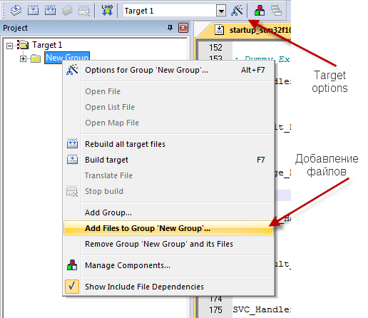
With the selected root of the Target 1 project tree, we call up the Target Options settings, and configure each tab as shown below:


After that click Build (F7) and see in the status line:
"__.axf" - 0 Error(s), 0 Warning(s).Firmware and debugging
In order to flash our board, you need to click the Download button on the Keil toolbar. Here I encountered a second difficulty. The board did not want to be stitched and gave the error "NO ST-Link Detected". The problem was solved by replacing the Keil \ ARM \ STLink \ STLinkUSBDriver.dll driver with an older one that can be found here . After that, the board is stitched, and debugging is launched by Ctrl + F5. Pressing the cherished Reset button allows you to see how the demo board reacts to the rotation of the trimmer:
findings
This topic is certainly not for one topic, I have already delayed the final. I deliberately did not go into the details of setting up blocks of the model and circuit design. But the fact that the time to create a prototype of the product is reduced by several times I think can be seen with the naked eye. With the help of Simulink and Stateflow (event-oriented development based on the theory of finite automata), literally "on the knee" you can assemble an extremely complex control system. Here we are limited only by the capabilities of the hardware and to have a concept in modeling, and the development time is no longer the decisive factor.
If the topic is interesting, I can please with a couple more topics dedicated to Model-based design .
Thank you for attention!
Information sources
Attachments
UPDATE 1:
Screenshot of checking the logic of the model before generating code:

Source: https://habr.com/ru/post/129519/
All Articles