The simplest logical circuit. Part 2: rules for connecting modules to each other and analyzing simple logic circuits
Greetings to all.
I continue writing articles about the simplest logical chains.
In this post - the rules for connecting logic elements and circuits between themselves, as well as two simple methods for analyzing logic circuits.
Due to numerous requests of habra people, as well as to simplify the perception of what was written, I will give, in addition to the western name of a certain element, Russian.
In the last article we met with such logical modules as Not-1 (logical negation,! A), Or-2 (logical sum, AvB) and And-2 (logical multiplication, A ^ B), but not a word was said how to interconnect these simplest combinational logic circuits (KLC, they are also combinational circuits).
')
Here are some rules that will help avoid errors when connecting conductors and logic modules:
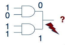
1. Do not connect the two outputs directly. This can lead to signal conflicts.
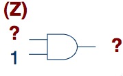
2. If a logical module has two inputs, both of them should have a value. If the signal at one of the inputs is unknown, then most likely it will not be possible to know the value of the outgoing signal.
3. There should be no cycles. The effect can be any - from the instability of the chain to its inability to function.

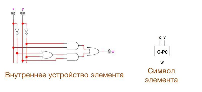
To simplify the analysis of the circuits, we will use some conventions. For example:
As you can see, a certain set of elements is depicted using a single module.
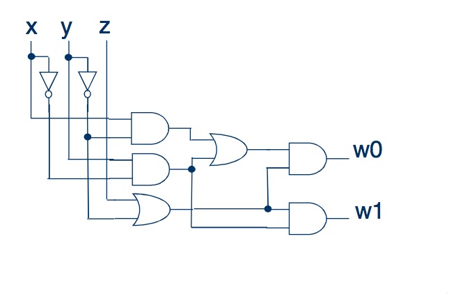
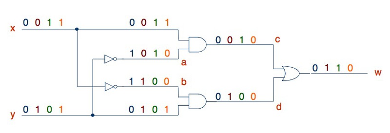
Take any combination scheme made according to the rules. For example this:
The essence of circuit analysis is to identify outgoing signals, depending on the values of the inputs.
There are two methods of this analysis itself - horizontal (in rows) and vertical (in columns).
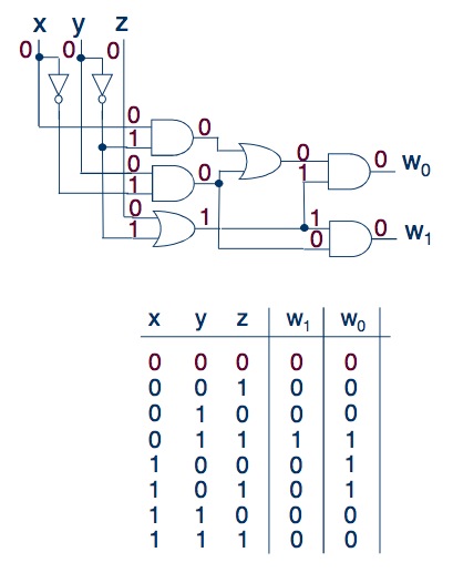
This type of study of the circuits is as follows: we alternately set different values at the inputs of the circuit, and see how the signal changes as it travels further along the circuit. Here is a good example:
In this way it is convenient to analyze small schemes with one or two inputs, because it is not necessary to build a truth table.
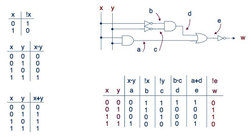
For such chains as we have chosen earlier, it is better to draw this same table and enter the values found there. So, for example:
The essence of this method is alternately, using logical expressions, to find values for all parts of the circuit, and only then calculate the result for the outputs of the circuit.
As seen in the picture, we calculate the signal values for each element of the circuit, gradually approaching the output. For our chain, it will look like this:
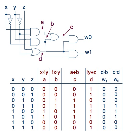
Now you can compare the results obtained using the two methods. If they match, it means that either everything was done correctly, or we made more than one error (:-D).
In the next article we will begin to create our own logic for the given parameters.
Continuation will be very soon.
Thank you for your attention, and have a great weekend!
I continue writing articles about the simplest logical chains.
In this post - the rules for connecting logic elements and circuits between themselves, as well as two simple methods for analyzing logic circuits.
Due to numerous requests of habra people, as well as to simplify the perception of what was written, I will give, in addition to the western name of a certain element, Russian.
Rules for connecting chains and their components
In the last article we met with such logical modules as Not-1 (logical negation,! A), Or-2 (logical sum, AvB) and And-2 (logical multiplication, A ^ B), but not a word was said how to interconnect these simplest combinational logic circuits (KLC, they are also combinational circuits).
')
Here are some rules that will help avoid errors when connecting conductors and logic modules:
1. Do not connect the two outputs directly. This can lead to signal conflicts.
2. If a logical module has two inputs, both of them should have a value. If the signal at one of the inputs is unknown, then most likely it will not be possible to know the value of the outgoing signal.
3. There should be no cycles. The effect can be any - from the instability of the chain to its inability to function.
Logic analysis
To simplify the analysis of the circuits, we will use some conventions. For example:
As you can see, a certain set of elements is depicted using a single module.
Chain analysis of 6-8 elements
Take any combination scheme made according to the rules. For example this:
If you for some reason do not like my scheme, draw your own :-)
The essence of circuit analysis is to identify outgoing signals, depending on the values of the inputs.
There are two methods of this analysis itself - horizontal (in rows) and vertical (in columns).
Row analysis
This type of study of the circuits is as follows: we alternately set different values at the inputs of the circuit, and see how the signal changes as it travels further along the circuit. Here is a good example:
In this way it is convenient to analyze small schemes with one or two inputs, because it is not necessary to build a truth table.
For such chains as we have chosen earlier, it is better to draw this same table and enter the values found there. So, for example:
Column analysis
The essence of this method is alternately, using logical expressions, to find values for all parts of the circuit, and only then calculate the result for the outputs of the circuit.
As seen in the picture, we calculate the signal values for each element of the circuit, gradually approaching the output. For our chain, it will look like this:
Now you can compare the results obtained using the two methods. If they match, it means that either everything was done correctly, or we made more than one error (:-D).
At the moment everything.
In the next article we will begin to create our own logic for the given parameters.
Continuation will be very soon.
Thank you for your attention, and have a great weekend!
Source: https://habr.com/ru/post/129516/
All Articles