We draw water on Direct3D. Part 1. Graphics pipeline architecture and API
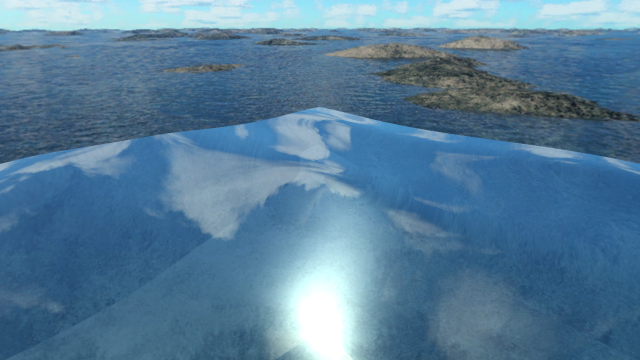
In this article, divided into several parts, I will explain in general terms the architecture of modern versions of Direct3D (10-11), and also show how using this API to draw just such a scene of a coral reef, the main advantage of which is simple to implement, but beautiful and relatively convincing looking water:
You should start by describing the Direct3D architecture.
API Direct3D is a direct reflection of the architecture of modern video cards, and encapsulates the following graphic pipeline:
')
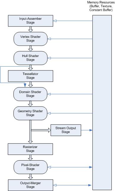
In the figure, the fully programmable stages of the conveyor are indicated by rounded rectangles, and the configurable are ordinary.
Now I will explain each of the stages separately.
Input Assembler (IA for short) - retrieves data about vertices from buffers located in system memory and collects from them primitives that are used by subsequent stages of the pipeline. Also, IA attaches to the vertices some metadata generated by the D3D runtime, such as the vertex number.
Vertex Shader (Vertex Shader, VS) is a mandatory, and fully programmable stage of the pipeline. As you can easily guess, it runs for each vertex (English vertex ), and receives input data from the Input Assembler. It is used for various transformations of vertices, for transformation of their coordinates from one coordinate system to another, for generating normals, texture coordinates, lighting calculations and another. The data from the vertex shader come either directly to the rasterizer, or to the Stream Output (if this stage of the pipeline is set, but the geometric shader is not), or to the geometric shader, or to the surface shader.
Hull Shader (surface shader, HS), Domain Shader (domain shader, DS) and Tesselator (tesselator) are the stages added to Shader Model 5.0 (and D3D11, respectively) and used during the tessellation process (splitting primitives into smaller ones for enhance image detail). These pipeline stages are optional, and since they are not used in my scene, I will not dwell on them in detail. Those interested can read about them, for example, on MSDN .
Geometry Shader (geometric shader, GS) - handles primitives (points, lines or triangles) collected from vertices processed by previous stages of the pipeline. Geometric shaders can generate new primitives on the fly (that is, their exhaust does not have to be 1-to-1, as in the case of, for example, vertex shaders). They are used to generate shadow geometry (shadow volume), sprites (particle systems, etc.), reflections (for example, one-pass drawing in a cube map) and the like. Although it can be used for tessellation, it is not recommended. The data from the geometry shader is fed either to the Stream Output or to the rasterizer.
Stream Output (SO) - an optional stage of the pipeline, used to unload the vertices processed by the pipeline back to the system memory (so that the exhaust SO can be read by the CPU or used by the pipeline the next time it is started). Data is received either from a geometric shader, or, in the case of its absence, from a vertex or domain.
Rasterizer (rasterizer, RS) is the “heart” of the graphics pipeline. The purpose of this stage, as the name implies, is rasterization of primitives, that is, their splitting into pixels (although the name “pixel” is not entirely correct - a pixel usually means what is directly in the framebuffer, that is, what is displayed on the screen , so it would be more correct to "fragments"). The rasterizer will receive the vector information about the vertices from the previous stages of the pipeline, and convert it into raster, cutting off primitives outside the scope, interpolating the values associated with the vertices (such as texture coordinates) and projecting their positions on the two-dimensional viewing area (Eng. viewport ). Data from the rasterizer goes to the pixel shader, if it is installed.
Pixel Shader (pixel shader, PS) - works with image fragments obtained from the rasterizer. Used to implement a huge variety of graphic effects, and the output, in the Output Merger stage, gives the color of the fragment, and, optionally, the depth value (the value used to determine which fragments lie closer to the camera).
Output Merger (OM) - the last stage of the graphics pipeline. For each fragment received from the pixel shader, it performs a depth test and a stencil test, determining whether the fragment should get into the framebuffer and mixes colors, if included.
Now about the API itself.
The Direct3D API is based on the lightweight COM ( Microsoft Component Object Model ). Lightweight so that from the "full-fledged" COM there remains only the concept of interfaces.
For those who are unfamiliar with the concept of a COM interface, a small lyrical digression.
The concept of a COM interface is close in its essence to the concept of interfaces from .NET (because .NET is, in fact, a development of COM). At its core, this is an abstract class that has only methods, and which is associated with some 16-byte identifier ( GUID ). Physically, an interface is a collection of functions, that is, a pointer to an array with pointers to functions (with a C-compatible ABI, and usually with a stdcall call convention), whose first argument is a pointer to the interface itself. Behind each interface is some object that implements it, and each object can implement several different types of interfaces. Microsoft postulates that the only way to communicate with an object that implements an interface is through a pointer to this interface, namely, by calling its methods.
Interfaces can be inherited from each other, and most COM interfaces, including Direct3D, are inherited from a special interface — IUnknown , which implements controlling the lifetime of an object that implements the interface through reference counting and allows you to receive pointers to interfaces of various types from the object by their GUID.
I must say that although the program for this article is written in C ++, but since COM interfaces have C-compatible ABI, you can work with them from any language that is able to work with native code, directly or through FFI . In the case of MSVC ++ and .NET, this is particularly convenient, since MS seamlessly integrated COM into C ++ and .NET object systems, respectively.
Interfaces Direct3D 10 and 11 can be divided into several types:
DXGI Interfaces DXGI is a low-level API on which all new components of the Windows graphics subsystem are based. In the case of D3D, we are especially interested in the IDXGISwapChain interface - it encapsulates a chain of buffers into which the graphics pipeline draws, and is responsible for linking them to a specific winapi window (HWND). Although it is not necessary to use this interface (even for drawing “to the window” - we can draw into texture and then transfer it to HDC in GDI), it is often used, as it is very convenient.
Interfaces of the virtual adapter. Used to create various resources, to configure the graphics pipeline and to start it. In D3D10, one interface was responsible for all this, ID3D10Device (or ID3D10Device1 , for D3D10.1. In general, in the naming of D3D and DXGI interfaces - the prefix “I” in the name means that the type is an interface type, a prefix like “DXGI” or “ D3D11 "means a specific API, and the suffix, if there is one, means the minor version of the API), in D3D11 it was divided into two - ID3D11Device (resource creation), and ID3D11DeviceContext (the remaining two tasks).
Objects that implement these interfaces also implement some DXGI interfaces — for example, we can query the IDXGIDevice interface from ID3D11Device (by calling the QueryInterface method (which is included in IUnknown , and ID3D11Device is inherited from IUnknown ) from the first)
Here we should mention that using the newest API, we absolutely do not have to require the hardware on which our program will work to fully comply with this API. In D3D10.1, Microsoft introduced the concept of “feature level”, which allows programs using new API versions to run even on D3D9 hardware (if they do not require features from the API, of a certain feature level that are not included, of course). In the case of my scene, I will use D3D11, but I will create a virtual adapter with the D3D_FEATURE_LEVEL_10_0 flag, and use the 4th model shaders respectively.
Auxiliary interfaces. Such as ID3D11Debug , ID3D11InfoQueue , ID3D11Counter or ID3D11ShaderReflection - used to get additional information about the status of the pipeline, about shaders, to measure performance and other.
Resource Interfaces In D3D, a resource is some kind of texture (for example, ID3D11Texture2D is a two-dimensional texture), or just a buffer (containing, for example, vertex data). Resource objects also implement various DXGI interfaces, such as IDXGIResource , and this is the key to interoperability between different graphics subsystems (such as Direct2D, GDI) and different versions of the same subsystem (D3D9, 10 and 11) in new versions of Windows.
Interfaces of representation (English view ). Each resource we can use for several different purposes, and perhaps even at the same time. In new versions of D3D, we do not supply textures and buffers interfaces directly to the pipeline (except for vertex buffers, indexes, and constants), instead we create an object that implements one of the presentation interfaces and deliver it to the pipeline.
In D3D11, the following types of view interfaces are present:
Shader Interfaces For example, ID3D11VertexShader . Encapsulate the shader code for a specific programmable stage of the graphics pipeline, and are used to set up the shader for this stage.
Interfaces of a state (English state ). Used to configure various non-programmable pipeline stages. Examples are ID3D11RasterizerState (configures the rasterizer), ID3D11InputLayout (stores information about the vertices supplied from the vertex buffers in the Input Assembler), ID3D11BlendState (configures the color mixing process in Output Merger).
Actually, the program that paints the scene mentioned at the very beginning will be described in the following parts of the article, namely, in the second part I will describe in detail the process of creating and initializing the virtual adapter and the resources needed to render the scene, and the third part will be devoted to the shaders used in the program .
The full code is available on github, at the following link: github.com/Lovesan/Reef
You should start by describing the Direct3D architecture.
API Direct3D is a direct reflection of the architecture of modern video cards, and encapsulates the following graphic pipeline:
')
In the figure, the fully programmable stages of the conveyor are indicated by rounded rectangles, and the configurable are ordinary.
Now I will explain each of the stages separately.
Input Assembler (IA for short) - retrieves data about vertices from buffers located in system memory and collects from them primitives that are used by subsequent stages of the pipeline. Also, IA attaches to the vertices some metadata generated by the D3D runtime, such as the vertex number.
Vertex Shader (Vertex Shader, VS) is a mandatory, and fully programmable stage of the pipeline. As you can easily guess, it runs for each vertex (English vertex ), and receives input data from the Input Assembler. It is used for various transformations of vertices, for transformation of their coordinates from one coordinate system to another, for generating normals, texture coordinates, lighting calculations and another. The data from the vertex shader come either directly to the rasterizer, or to the Stream Output (if this stage of the pipeline is set, but the geometric shader is not), or to the geometric shader, or to the surface shader.
Hull Shader (surface shader, HS), Domain Shader (domain shader, DS) and Tesselator (tesselator) are the stages added to Shader Model 5.0 (and D3D11, respectively) and used during the tessellation process (splitting primitives into smaller ones for enhance image detail). These pipeline stages are optional, and since they are not used in my scene, I will not dwell on them in detail. Those interested can read about them, for example, on MSDN .
Geometry Shader (geometric shader, GS) - handles primitives (points, lines or triangles) collected from vertices processed by previous stages of the pipeline. Geometric shaders can generate new primitives on the fly (that is, their exhaust does not have to be 1-to-1, as in the case of, for example, vertex shaders). They are used to generate shadow geometry (shadow volume), sprites (particle systems, etc.), reflections (for example, one-pass drawing in a cube map) and the like. Although it can be used for tessellation, it is not recommended. The data from the geometry shader is fed either to the Stream Output or to the rasterizer.
Stream Output (SO) - an optional stage of the pipeline, used to unload the vertices processed by the pipeline back to the system memory (so that the exhaust SO can be read by the CPU or used by the pipeline the next time it is started). Data is received either from a geometric shader, or, in the case of its absence, from a vertex or domain.
Rasterizer (rasterizer, RS) is the “heart” of the graphics pipeline. The purpose of this stage, as the name implies, is rasterization of primitives, that is, their splitting into pixels (although the name “pixel” is not entirely correct - a pixel usually means what is directly in the framebuffer, that is, what is displayed on the screen , so it would be more correct to "fragments"). The rasterizer will receive the vector information about the vertices from the previous stages of the pipeline, and convert it into raster, cutting off primitives outside the scope, interpolating the values associated with the vertices (such as texture coordinates) and projecting their positions on the two-dimensional viewing area (Eng. viewport ). Data from the rasterizer goes to the pixel shader, if it is installed.
Pixel Shader (pixel shader, PS) - works with image fragments obtained from the rasterizer. Used to implement a huge variety of graphic effects, and the output, in the Output Merger stage, gives the color of the fragment, and, optionally, the depth value (the value used to determine which fragments lie closer to the camera).
Output Merger (OM) - the last stage of the graphics pipeline. For each fragment received from the pixel shader, it performs a depth test and a stencil test, determining whether the fragment should get into the framebuffer and mixes colors, if included.
Now about the API itself.
The Direct3D API is based on the lightweight COM ( Microsoft Component Object Model ). Lightweight so that from the "full-fledged" COM there remains only the concept of interfaces.
For those who are unfamiliar with the concept of a COM interface, a small lyrical digression.
The concept of a COM interface is close in its essence to the concept of interfaces from .NET (because .NET is, in fact, a development of COM). At its core, this is an abstract class that has only methods, and which is associated with some 16-byte identifier ( GUID ). Physically, an interface is a collection of functions, that is, a pointer to an array with pointers to functions (with a C-compatible ABI, and usually with a stdcall call convention), whose first argument is a pointer to the interface itself. Behind each interface is some object that implements it, and each object can implement several different types of interfaces. Microsoft postulates that the only way to communicate with an object that implements an interface is through a pointer to this interface, namely, by calling its methods.
Interfaces can be inherited from each other, and most COM interfaces, including Direct3D, are inherited from a special interface — IUnknown , which implements controlling the lifetime of an object that implements the interface through reference counting and allows you to receive pointers to interfaces of various types from the object by their GUID.
I must say that although the program for this article is written in C ++, but since COM interfaces have C-compatible ABI, you can work with them from any language that is able to work with native code, directly or through FFI . In the case of MSVC ++ and .NET, this is particularly convenient, since MS seamlessly integrated COM into C ++ and .NET object systems, respectively.
Interfaces Direct3D 10 and 11 can be divided into several types:
DXGI Interfaces DXGI is a low-level API on which all new components of the Windows graphics subsystem are based. In the case of D3D, we are especially interested in the IDXGISwapChain interface - it encapsulates a chain of buffers into which the graphics pipeline draws, and is responsible for linking them to a specific winapi window (HWND). Although it is not necessary to use this interface (even for drawing “to the window” - we can draw into texture and then transfer it to HDC in GDI), it is often used, as it is very convenient.
Interfaces of the virtual adapter. Used to create various resources, to configure the graphics pipeline and to start it. In D3D10, one interface was responsible for all this, ID3D10Device (or ID3D10Device1 , for D3D10.1. In general, in the naming of D3D and DXGI interfaces - the prefix “I” in the name means that the type is an interface type, a prefix like “DXGI” or “ D3D11 "means a specific API, and the suffix, if there is one, means the minor version of the API), in D3D11 it was divided into two - ID3D11Device (resource creation), and ID3D11DeviceContext (the remaining two tasks).
Objects that implement these interfaces also implement some DXGI interfaces — for example, we can query the IDXGIDevice interface from ID3D11Device (by calling the QueryInterface method (which is included in IUnknown , and ID3D11Device is inherited from IUnknown ) from the first)
Here we should mention that using the newest API, we absolutely do not have to require the hardware on which our program will work to fully comply with this API. In D3D10.1, Microsoft introduced the concept of “feature level”, which allows programs using new API versions to run even on D3D9 hardware (if they do not require features from the API, of a certain feature level that are not included, of course). In the case of my scene, I will use D3D11, but I will create a virtual adapter with the D3D_FEATURE_LEVEL_10_0 flag, and use the 4th model shaders respectively.
Auxiliary interfaces. Such as ID3D11Debug , ID3D11InfoQueue , ID3D11Counter or ID3D11ShaderReflection - used to get additional information about the status of the pipeline, about shaders, to measure performance and other.
Resource Interfaces In D3D, a resource is some kind of texture (for example, ID3D11Texture2D is a two-dimensional texture), or just a buffer (containing, for example, vertex data). Resource objects also implement various DXGI interfaces, such as IDXGIResource , and this is the key to interoperability between different graphics subsystems (such as Direct2D, GDI) and different versions of the same subsystem (D3D9, 10 and 11) in new versions of Windows.
Interfaces of representation (English view ). Each resource we can use for several different purposes, and perhaps even at the same time. In new versions of D3D, we do not supply textures and buffers interfaces directly to the pipeline (except for vertex buffers, indexes, and constants), instead we create an object that implements one of the presentation interfaces and deliver it to the pipeline.
In D3D11, the following types of view interfaces are present:
- ID3D11RenderTargetView - rendering target view (render target). As the name implies (in general, I must say, the type names in D3D and DXGI are very speaking, albeit long), to the resource associated with this representation, the graphics pipeline draws
- ID3D11ShaderResourceView - a view for the resources used by shaders (an example is the texture from which the pixel shader selects a texel to form a fragment color).
- ID3D11DepthStencilView is a view for resources used as a depth buffer and stencil.
- ID3D11UnorderedAccessView - a view for the resources used by compute shaders (Compute Shader, CS - since they practically do not belong to the rendering process, I will not describe them).
Shader Interfaces For example, ID3D11VertexShader . Encapsulate the shader code for a specific programmable stage of the graphics pipeline, and are used to set up the shader for this stage.
Interfaces of a state (English state ). Used to configure various non-programmable pipeline stages. Examples are ID3D11RasterizerState (configures the rasterizer), ID3D11InputLayout (stores information about the vertices supplied from the vertex buffers in the Input Assembler), ID3D11BlendState (configures the color mixing process in Output Merger).
Actually, the program that paints the scene mentioned at the very beginning will be described in the following parts of the article, namely, in the second part I will describe in detail the process of creating and initializing the virtual adapter and the resources needed to render the scene, and the third part will be devoted to the shaders used in the program .
The full code is available on github, at the following link: github.com/Lovesan/Reef
Source: https://habr.com/ru/post/129166/
All Articles