The simplest logical circuit. Part 1: General Information on Logic Circuits and Simple Logic Modules
Greetings to all.
I decided to write a few articles about the simplest logical circuits.
This topic will be interesting rather for people who have a weak idea of the algebra of logic and logical constructions, than for professionals and experts on this topic.
So, let's begin.
This is a circuit capable of processing binary electrical signals. At each time point, the outgoing signals of the combining logic circuit (MFC) depend exclusively on the incoming signals. Therefore, the same combination of incoming values corresponds to the same combination of outgoing values.
Characteristic of the KLC is a lack of memory. Ie, signals that previously entered the circuit do not matter. (“The current moment is important,” said one of the characters in the film “21”.)
')
For a better understanding, analysis and image of complex circuits, their somewhat simplified mathematical models are used.
In most models, during the development of a QLC, the interaction time of the circuit elements is not taken into account. Therefore, we will assume that the output signals of the circuit instantly react to changes in the incoming signals. Also, instead of the signal function of time x (t), which can change its essence depending on the technology used (for example, 0 and 5 volts in TTL; 0 and 3.1 volts in CMOS), we will use the logic function x, which can take values 0 and 1.
To describe the work of the KLC, the so-called truth table is used. This table indicates the output values for specific input values. It might look like this:
In the truth table, the values of each of the signals are arranged in columns, and the rows indicate the correspondence between the signals.
I will give an example of a logical problem that is solved using such a table.
Let's say that we have a water tower. To create the necessary pressure in the pipeline system, a certain amount of water must be in the tower around the clock. But it is impossible to get water into the tower all the time - it is not dimensionless, and electric energy is not cheap. We need to create a controller that will turn on and off the water supply to the tower, depending on several indicators.

The picture shows several sensors:
X is the time of day, where 1 is day and 0 is night (electricity is cheaper at night);
Y and Z are humidity sensors, for them 1 is water, and 0 is dry.
W will control the valve by turning it on (1) and off (0) if necessary.
Truth tables for this case will look like this:

a) we simply list all possible combinations of indications X, Y and Z;
b) we look at the simplest options: if both Y and Z are set to 0, then this means that there is no water at all, so W must be turned on, and it doesn't matter whether it is night now or day. If both Y and Z have the value 1, then this means that the tank is full, respectively, W must be turned off;
c) Now about saving: if Z = 1, and Y = 0, then the water level in the tank is between two sensors. At the same time, if this happens at night (X = 0), then it is necessary to draw water to the maximum (W = 1), and during the day (X = 1 (- leave everything as it is (W = 0);
d) without incredible nowhere: there is a chance that Y will have the value 1 at Z = 0. Then, logically, we should send a fault message in the system, but we just show that this simply can not be.
Consider the simplest MFC: modules Not-1, And-2 and Or-2.
This is the simplest KLC, with one input and one output. The function of this module is to output the value opposite to the input. Since there is only one input, there are only two options:

This module is already a little more complicated. He has two entrances and one exit. The function of the And-2 module is as follows: the output will have the value 1 only if both inputs are also equal to one:
Now another module with two inputs and one output. Only now output 1 will be if at least one of the inputs has a value of 1:
One of these days I will write a few more articles - on the queue multiplexers, half-and full-adder'y, as well as various combinations of modules.
Thanks for attention.
I decided to write a few articles about the simplest logical circuits.
This topic will be interesting rather for people who have a weak idea of the algebra of logic and logical constructions, than for professionals and experts on this topic.
So, let's begin.
What is a combination logic circuit?
This is a circuit capable of processing binary electrical signals. At each time point, the outgoing signals of the combining logic circuit (MFC) depend exclusively on the incoming signals. Therefore, the same combination of incoming values corresponds to the same combination of outgoing values.
Characteristic of the KLC is a lack of memory. Ie, signals that previously entered the circuit do not matter. (“The current moment is important,” said one of the characters in the film “21”.)
')
Mathematical model of KLC
For a better understanding, analysis and image of complex circuits, their somewhat simplified mathematical models are used.
In most models, during the development of a QLC, the interaction time of the circuit elements is not taken into account. Therefore, we will assume that the output signals of the circuit instantly react to changes in the incoming signals. Also, instead of the signal function of time x (t), which can change its essence depending on the technology used (for example, 0 and 5 volts in TTL; 0 and 3.1 volts in CMOS), we will use the logic function x, which can take values 0 and 1.
Job description KLC
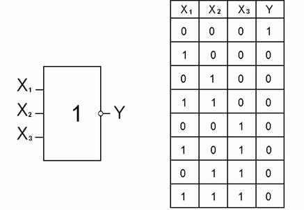
To describe the work of the KLC, the so-called truth table is used. This table indicates the output values for specific input values. It might look like this:
In the truth table, the values of each of the signals are arranged in columns, and the rows indicate the correspondence between the signals.
I will give an example of a logical problem that is solved using such a table.
Let's say that we have a water tower. To create the necessary pressure in the pipeline system, a certain amount of water must be in the tower around the clock. But it is impossible to get water into the tower all the time - it is not dimensionless, and electric energy is not cheap. We need to create a controller that will turn on and off the water supply to the tower, depending on several indicators.
The picture shows several sensors:
X is the time of day, where 1 is day and 0 is night (electricity is cheaper at night);
Y and Z are humidity sensors, for them 1 is water, and 0 is dry.
W will control the valve by turning it on (1) and off (0) if necessary.
Truth tables for this case will look like this:
a) we simply list all possible combinations of indications X, Y and Z;
b) we look at the simplest options: if both Y and Z are set to 0, then this means that there is no water at all, so W must be turned on, and it doesn't matter whether it is night now or day. If both Y and Z have the value 1, then this means that the tank is full, respectively, W must be turned off;
c) Now about saving: if Z = 1, and Y = 0, then the water level in the tank is between two sensors. At the same time, if this happens at night (X = 0), then it is necessary to draw water to the maximum (W = 1), and during the day (X = 1 (- leave everything as it is (W = 0);
d) without incredible nowhere: there is a chance that Y will have the value 1 at Z = 0. Then, logically, we should send a fault message in the system, but we just show that this simply can not be.
Simple logic modules
Consider the simplest MFC: modules Not-1, And-2 and Or-2.
Not-1
This is the simplest KLC, with one input and one output. The function of this module is to output the value opposite to the input. Since there is only one input, there are only two options:
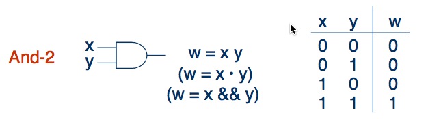
And-2
This module is already a little more complicated. He has two entrances and one exit. The function of the And-2 module is as follows: the output will have the value 1 only if both inputs are also equal to one:
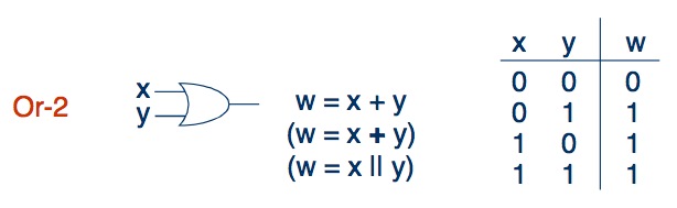
Or-2
Now another module with two inputs and one output. Only now output 1 will be if at least one of the inputs has a value of 1:
To be continued.
One of these days I will write a few more articles - on the queue multiplexers, half-and full-adder'y, as well as various combinations of modules.
Thanks for attention.
Source: https://habr.com/ru/post/129060/
All Articles