Memory organization
Over the last week, I twice explained to people how work with memory was organized in x86, in order not to explain for the third time I wrote this article.
And so, to understand the organization of memory, you will need knowledge of some basic concepts, such as registers, stack, and so on. I will try to explain this on my fingers as well, but very briefly because this is not the topic for this article. So, let's begin.
As you know, a programmer when writing programs does not work with a physical address, but only with a logical one. And then if he programs in assembler. In the same C, the memory cells from the programmer are already hidden by the pointers, for its convenience, but if it is rough to say the pointer is a different representation of the logical memory address, but in Java and pointers there is no, a completely bad language. However, the knowledgeable programmer will not be prevented from knowing how memory is organized, at least at a general level. I’m generally saddened by programmers who don’t know how the machine works, usually Java programmers and other php guys who have skills below the baseboard.
')
So okay, enough about the sad, get down to business.
Consider the 32-bit program mode address space (for 64-bit, all by analogy)
The address space of this mode will consist of 2 ^ 32 memory cells numbered from 0 to 2 ^ 32-1.
The programmer works with this memory, if he needs to define a variable, he simply says the memory cell with the address will contain such and such data type, while the programmer himself may not know what number this cell will just write something like :
int data = 10;
the computer will understand it this way: you need to take some kind of cell with the number of stopsets and put the integer number 10 into it. Moreover, you will not know about the cell address 18894, it will be hidden from you.
Everything would be fine, but the question arises, how does the computer look for this memory cell, because we can have different memory:
Level 3 cache
Cache level 2
Cache level 1
main memory
HDD
These are all different memories, but the computer easily finds in which of them our variable int data lies.
This issue is solved by the operating system together with the processor.
All further article will be devoted to the analysis of this method.
The x86 architecture supports the stack.
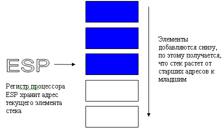
A stack is a continuous area of RAM organized according to the principle of a stack of plates; you cannot take plates from the middle of the stack; you can only take the top one and put the plate on top of the stack too.
In the processor for working with the stack, special machine codes are organized, the assembler mnemonics of which look like this:
push operand
pushes an operand on the stack
pop operand
removes a value from the top of the stack and places it in its operand
The stack in memory grows from top to bottom, which means that when you add a value to it, the address of the top of the stack decreases, and when you extract from it, the address of the top of the stack increases.
Now let's take a quick look at what registers are.
These are memory cells in the processor itself. This is the fastest and most expensive type of memory, when the processor performs some operations with a value or with memory, it takes these values directly from the registers.
The processor has several sets of logic, each of which has its own machine codes and its own set of registers.
Basic program registers These registers are used by all programs with their help, processing of integer data is performed.
Floating Point Unit registers (FPU) These registers work with data presented in floating point format.
MMX and XMM registers still exist; these registers are used when you need to execute one instruction on a large number of operands.
Let us consider in more detail the main program registers. These include eight 32-bit general purpose registers: EAX, EBX, ECX, EDX, EBP, ESI, EDI, ESP
To place data in a register, or to remove data from a register into a memory cell, use the mov command:
mov eax, 10
loads the number 10 into the eax register.
mov data, ebx
copies the number contained in the ebx register to the data memory.
The ESP register contains the address of the top of the stack.
In addition to general-purpose registers, the main program registers include six 16-bit segment registers: CS, DS, SS, ES, FS, GS, EFLAGS, EIP
EFLAGS displays bits, so-called flags, which reflect the state of the processor or indicate the progress of previous commands.
The EIP register contains the address of the next command that will be executed by the processor.
I will not paint the FPU registers, since we will not need them. So our small digression about the registers and the stack is over, let's go back to the memory organization.
As you remember, the purpose of this article is to tell about the transformation of logical memory into physical memory, in fact there is still an intermediate stage and the full chain looks like this:
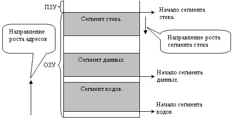
All linear address space is divided into segments. The address space of each process has at least three segments:
Code segment. (contains teams from our program that will be executed.)
The data segment. (Contains data, I mean variables)
The stack segment about which I wrote above.
Linear address is calculated by the formula:
The base address of the code segment is taken from the CS register. The offset value for the code segment is taken from the EIP register, which stores the address of the instruction, after the execution of which, the EIP value is increased by the size of this command. If the command takes 4 bytes, then the EIP value is increased by 4 bytes and will indicate the next instruction already. All this is done automatically without the participation of the programmer.
Code segments can be several in our memory. In our case, he is alone.
Data is loaded into DS, ES, FS, GS registers.
This means that data segments can be up to 4x. In our picture he is alone.
The offset inside the data segment is specified as the operand of the command. By default, the segment is indicated by the register DS. In order to enter another segment it is necessary to indicate this directly in the command of the segment replacement prefix.
The stack segment used is specified by the value of the SS register.
The offset inside this segment is represented by the ESP register, which points to the top of the stack, as you remember.
Segments in memory can overlap each other, moreover, the base address of all segments may coincide, for example, at zero. Such a degenerate case is called a linear representation of memory. In modern systems, memory is usually so organized.
Now consider the definition of the base addresses of the segment, I wrote that they are contained in the registers SS, DS, CS, but this is not quite so, they contain some 16-bit selector that points to a certain descriptor of segments, which already stores the necessary address.
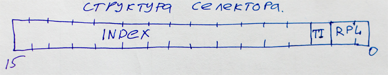
This is what the selector looks like, its thirteen bits contain the index of the descriptor in the descriptor table. It’s not tricky to calculate that 2 ^ 13 = 8192 is the maximum number of descriptors in a table.
In general, descriptor tables are two types of GDT and LDT. The first is called a global table of descriptors, it is always only one in the system, its starting address, more precisely, the address of its zero descriptor is stored in the 48-bit system GDTR register. And since the start of the system does not change and does not participate in the swap.
But the values of the descriptors may vary. If the TI bit in the selector is zero, then the processor simply goes to the GDT to search by index for the desired descriptor with which it accesses this segment.
So far everything has been simple, but if TI is equal to 1 then this means that the LDT will be used. There are a lot of these tables, but the currently used selector will be the one that is loaded into the LDTR system register, which, unlike GDTR, can be changed.
The selector index points to a descriptor that no longer points to the base address of the segment, but to the memory in which the local table of descriptors is stored, or rather its zero element. Well, then everything is the same as with GDT. Thus, during operation, local tables can be created and destroyed as needed. LDTs cannot contain handles to other LDTs.
So, we know how the processor gets to the descriptor, and what is contained in this descriptor will look at the picture: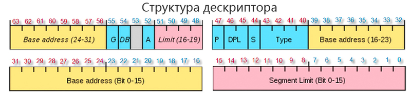
Descriptors consists of 8 bytes.
Bits 15-39 and 56-63 contain the linear base address described by this segment descriptor. Let me remind our formula for finding a linear address:
With such a simple operation, the processor can access the desired linear memory address.
Consider the other bits of the descriptor, the Segment Limit or the limit is very important, it has a 20-bit value between 0-15 and 48-51 bits. The limit sets the size of the segment. For data and code segments, all addresses located in the interval are available:
Depending on 55 G-bits (granularity), the limit can be measured in bytes with a zero value of the bit, and then the maximum limit is 1 mb, or 1, the limit is measured by pages, each of which is 4kb. and the maximum size of this segment will be 4GB.
For a stack segment, the limit will be in the interval:
By the way, I wonder why the base and the limit are so raggedly located in the descriptor. The fact is that x86 processors evolved evolutionarily and at the time of 286x the descriptors were 8 bits in total, while the older 2 bytes were reserved, well, in subsequent models of processors, the descriptors also grew with an increase in bit depth, but to maintain backward compatibility .
The value of the address “vertex” depends on the 54th D bit, if it is 0, then the vertex is 0xFFF (64kb-1), if the D bit is 1, then the vertex is 0xFFFFFFFF (4GB-1)
From 41-43 bits, the segment type is encoded.
000 - data segment, read only
001 - data segment, read and write
010 - stack segment, read only
011 - stack segment, read and write
100 - code segment, execution only
101- code segment, read and execute
110 - subordinate code segment, execution only
111 - subordinate code segment, only execution and reading
44 S bits if equal to 1 then the descriptor describes the real segment of the RAM, otherwise the value of the S bits is 0.
The most important bit is the 47th P bits of presence. If the bit is 1, it means that the segment or local table of descriptors is loaded into the RAM, if this bit is 0, then this means that there is no this segment in the RAM, it is on the hard disk, an interrupt happens, a special case of the processor is started which loads the desired segment from the hard disk into memory, if the P bits is 0, then all descriptor fields lose their meaning and become free to store service information in them. After the handler completes, the P bit is set to 1, and the handle is recalled, the segment of which is already in memory.
This ends the conversion of a logical address to a linear one, and I think this should be interrupted. Next time I will tell the second part of the conversion from linear to physical.
And I also think it is worth talking a little about passing the arguments of the function, and about the placement of variables in memory so that there is some connection with reality, because the placement of variables in memory is already immediate, what you have to deal with in work, and not just what - theoretical fabrications for the system programmer. But without understanding how memory works, it is impossible to understand how these variables are stored in memory.
In general, I hope it was interesting and see you soon.
And so, to understand the organization of memory, you will need knowledge of some basic concepts, such as registers, stack, and so on. I will try to explain this on my fingers as well, but very briefly because this is not the topic for this article. So, let's begin.
As you know, a programmer when writing programs does not work with a physical address, but only with a logical one. And then if he programs in assembler. In the same C, the memory cells from the programmer are already hidden by the pointers, for its convenience, but if it is rough to say the pointer is a different representation of the logical memory address, but in Java and pointers there is no, a completely bad language. However, the knowledgeable programmer will not be prevented from knowing how memory is organized, at least at a general level. I’m generally saddened by programmers who don’t know how the machine works, usually Java programmers and other php guys who have skills below the baseboard.
')
So okay, enough about the sad, get down to business.
Consider the 32-bit program mode address space (for 64-bit, all by analogy)
The address space of this mode will consist of 2 ^ 32 memory cells numbered from 0 to 2 ^ 32-1.
The programmer works with this memory, if he needs to define a variable, he simply says the memory cell with the address will contain such and such data type, while the programmer himself may not know what number this cell will just write something like :
int data = 10;
the computer will understand it this way: you need to take some kind of cell with the number of stopsets and put the integer number 10 into it. Moreover, you will not know about the cell address 18894, it will be hidden from you.
Everything would be fine, but the question arises, how does the computer look for this memory cell, because we can have different memory:
Level 3 cache
Cache level 2
Cache level 1
main memory
HDD
These are all different memories, but the computer easily finds in which of them our variable int data lies.
This issue is solved by the operating system together with the processor.
All further article will be devoted to the analysis of this method.
The x86 architecture supports the stack.
A stack is a continuous area of RAM organized according to the principle of a stack of plates; you cannot take plates from the middle of the stack; you can only take the top one and put the plate on top of the stack too.
In the processor for working with the stack, special machine codes are organized, the assembler mnemonics of which look like this:
push operand
pushes an operand on the stack
pop operand
removes a value from the top of the stack and places it in its operand
The stack in memory grows from top to bottom, which means that when you add a value to it, the address of the top of the stack decreases, and when you extract from it, the address of the top of the stack increases.
Now let's take a quick look at what registers are.
These are memory cells in the processor itself. This is the fastest and most expensive type of memory, when the processor performs some operations with a value or with memory, it takes these values directly from the registers.
The processor has several sets of logic, each of which has its own machine codes and its own set of registers.
Basic program registers These registers are used by all programs with their help, processing of integer data is performed.
Floating Point Unit registers (FPU) These registers work with data presented in floating point format.
MMX and XMM registers still exist; these registers are used when you need to execute one instruction on a large number of operands.
Let us consider in more detail the main program registers. These include eight 32-bit general purpose registers: EAX, EBX, ECX, EDX, EBP, ESI, EDI, ESP
To place data in a register, or to remove data from a register into a memory cell, use the mov command:
mov eax, 10
loads the number 10 into the eax register.
mov data, ebx
copies the number contained in the ebx register to the data memory.
The ESP register contains the address of the top of the stack.
In addition to general-purpose registers, the main program registers include six 16-bit segment registers: CS, DS, SS, ES, FS, GS, EFLAGS, EIP
EFLAGS displays bits, so-called flags, which reflect the state of the processor or indicate the progress of previous commands.
The EIP register contains the address of the next command that will be executed by the processor.
I will not paint the FPU registers, since we will not need them. So our small digression about the registers and the stack is over, let's go back to the memory organization.
As you remember, the purpose of this article is to tell about the transformation of logical memory into physical memory, in fact there is still an intermediate stage and the full chain looks like this:
Logical address -> Linear (virtual) -> Physical
All linear address space is divided into segments. The address space of each process has at least three segments:
Code segment. (contains teams from our program that will be executed.)
The data segment. (Contains data, I mean variables)
The stack segment about which I wrote above.
Linear address is calculated by the formula:
linear address = Base address of the segment (in the picture this is the beginning of the segment) + offset
Code segment
The base address of the code segment is taken from the CS register. The offset value for the code segment is taken from the EIP register, which stores the address of the instruction, after the execution of which, the EIP value is increased by the size of this command. If the command takes 4 bytes, then the EIP value is increased by 4 bytes and will indicate the next instruction already. All this is done automatically without the participation of the programmer.
Code segments can be several in our memory. In our case, he is alone.
Data segment
Data is loaded into DS, ES, FS, GS registers.
This means that data segments can be up to 4x. In our picture he is alone.
The offset inside the data segment is specified as the operand of the command. By default, the segment is indicated by the register DS. In order to enter another segment it is necessary to indicate this directly in the command of the segment replacement prefix.
Stack segment
The stack segment used is specified by the value of the SS register.
The offset inside this segment is represented by the ESP register, which points to the top of the stack, as you remember.
Segments in memory can overlap each other, moreover, the base address of all segments may coincide, for example, at zero. Such a degenerate case is called a linear representation of memory. In modern systems, memory is usually so organized.
Now consider the definition of the base addresses of the segment, I wrote that they are contained in the registers SS, DS, CS, but this is not quite so, they contain some 16-bit selector that points to a certain descriptor of segments, which already stores the necessary address.
This is what the selector looks like, its thirteen bits contain the index of the descriptor in the descriptor table. It’s not tricky to calculate that 2 ^ 13 = 8192 is the maximum number of descriptors in a table.
In general, descriptor tables are two types of GDT and LDT. The first is called a global table of descriptors, it is always only one in the system, its starting address, more precisely, the address of its zero descriptor is stored in the 48-bit system GDTR register. And since the start of the system does not change and does not participate in the swap.
But the values of the descriptors may vary. If the TI bit in the selector is zero, then the processor simply goes to the GDT to search by index for the desired descriptor with which it accesses this segment.
So far everything has been simple, but if TI is equal to 1 then this means that the LDT will be used. There are a lot of these tables, but the currently used selector will be the one that is loaded into the LDTR system register, which, unlike GDTR, can be changed.
The selector index points to a descriptor that no longer points to the base address of the segment, but to the memory in which the local table of descriptors is stored, or rather its zero element. Well, then everything is the same as with GDT. Thus, during operation, local tables can be created and destroyed as needed. LDTs cannot contain handles to other LDTs.
So, we know how the processor gets to the descriptor, and what is contained in this descriptor will look at the picture:
Descriptors consists of 8 bytes.
Bits 15-39 and 56-63 contain the linear base address described by this segment descriptor. Let me remind our formula for finding a linear address:
linear address = base address + offset
With such a simple operation, the processor can access the desired linear memory address.
Consider the other bits of the descriptor, the Segment Limit or the limit is very important, it has a 20-bit value between 0-15 and 48-51 bits. The limit sets the size of the segment. For data and code segments, all addresses located in the interval are available:
[base; base + limit)
Depending on 55 G-bits (granularity), the limit can be measured in bytes with a zero value of the bit, and then the maximum limit is 1 mb, or 1, the limit is measured by pages, each of which is 4kb. and the maximum size of this segment will be 4GB.
For a stack segment, the limit will be in the interval:
(base + limit; vertex]
By the way, I wonder why the base and the limit are so raggedly located in the descriptor. The fact is that x86 processors evolved evolutionarily and at the time of 286x the descriptors were 8 bits in total, while the older 2 bytes were reserved, well, in subsequent models of processors, the descriptors also grew with an increase in bit depth, but to maintain backward compatibility .
The value of the address “vertex” depends on the 54th D bit, if it is 0, then the vertex is 0xFFF (64kb-1), if the D bit is 1, then the vertex is 0xFFFFFFFF (4GB-1)
From 41-43 bits, the segment type is encoded.
000 - data segment, read only
001 - data segment, read and write
010 - stack segment, read only
011 - stack segment, read and write
100 - code segment, execution only
101- code segment, read and execute
110 - subordinate code segment, execution only
111 - subordinate code segment, only execution and reading
44 S bits if equal to 1 then the descriptor describes the real segment of the RAM, otherwise the value of the S bits is 0.
The most important bit is the 47th P bits of presence. If the bit is 1, it means that the segment or local table of descriptors is loaded into the RAM, if this bit is 0, then this means that there is no this segment in the RAM, it is on the hard disk, an interrupt happens, a special case of the processor is started which loads the desired segment from the hard disk into memory, if the P bits is 0, then all descriptor fields lose their meaning and become free to store service information in them. After the handler completes, the P bit is set to 1, and the handle is recalled, the segment of which is already in memory.
This ends the conversion of a logical address to a linear one, and I think this should be interrupted. Next time I will tell the second part of the conversion from linear to physical.
And I also think it is worth talking a little about passing the arguments of the function, and about the placement of variables in memory so that there is some connection with reality, because the placement of variables in memory is already immediate, what you have to deal with in work, and not just what - theoretical fabrications for the system programmer. But without understanding how memory works, it is impossible to understand how these variables are stored in memory.
In general, I hope it was interesting and see you soon.
Source: https://habr.com/ru/post/128991/
All Articles