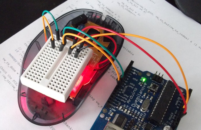
We receive the image from an optical sensor of a computer mouse by means of Arduino

To solve one of the tasks, I needed to programmatically obtain and process images of a small portion of the paper surface from a very close distance. Not having received decent quality when using a conventional USB camera and already half way to the store using an electron microscope, I remembered one of the lectures in which we were told how various devices are arranged, including a computer mouse.
Preparation and some theory
I will not go into details of the principle of operation of a modern optical mouse, it is written in great detail here (I recommend reading for general development).
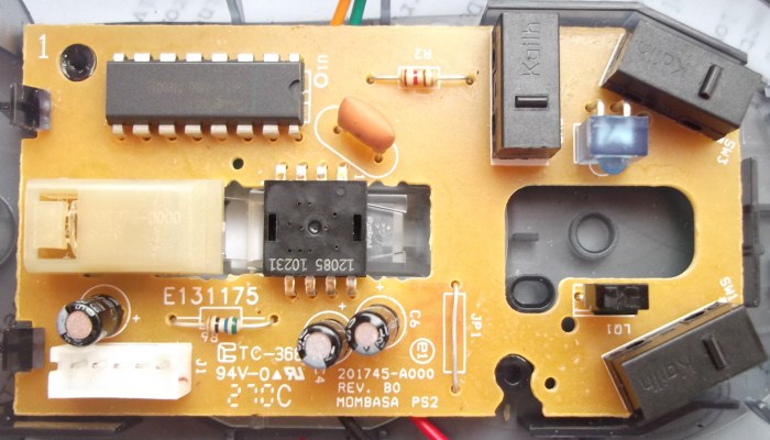
Googling information on this topic and disassembling an old Logitech PS / 2 mouse, I saw a familiar picture from the Internet.
')

The not so complicated scheme of the “first generation mice”, the optical sensor in the center and the PS / 2 interface chip are slightly higher. The optical sensor I got is an analogue of the “popular” models ADNS2610 / ADNS2620 / PAN3101. I think they and their counterparts were massively produced at the same Chinese factory, having received different markings at the output. The documentation for it was found very easy, even with various code examples.
Documentation says that this sensor, up to 1500 times per second, receives an image of a surface measuring 18x18 pixels (400cpi resolution), remembers it and, using image comparison algorithms, calculates the displacement along the X and Y coordinates relative to the previous position.
Implementation
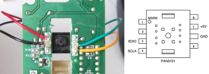
To “communicate with the sensor,” I used the popular computing platform Arduino, and decided to solder directly to the legs of the chip.

We connect 5V and GND to the corresponding outputs of the Arduino, and the SDIO and SCLK sensor legs to digital pins 8 and 9.
To get an offset by coordinates, you need to read the register value of the chip at 0x02 (X) and 0x03 (Y), and to dump the picture you need to first write the value 0x2A at 0x08, and then read it 18x18 times from there. This will be the last “memorized” value of the image brightness matrix from the optical sensor.
How I implemented it on Arduino can be found here: http://pastebin.com/YpRGbzAS (total ~ 100 lines of code).
And for receiving and displaying a picture, a program was written in Processing.
The source here: http://pastebin.com/XqGyP5EA .
Result
After a small “dopilivaniya” program for my project, I was able to get a picture directly from the optical sensor and make all the necessary calculations on it.

You can notice the texture of the surface (paper) and even the individual letters on it. It should be noted that such a clear picture quality is obtained due to the fact that the developers of this mouse model added a special glass stand with a small lens directly under the sensor to the design.
If you start raising the mouse above the surface, even a couple of millimeters, the clarity disappears immediately.

If you suddenly want to repeat this at home, to find a mouse with a similar sensor, I recommend looking for old devices with a PS / 2 interface.
Conclusion
Although the resulting image is not very large, this was quite enough to solve my problem (barcode scanner). It turned out very economically and quickly (a mouse for ~ 100 rubles + Arduino + a couple of days to write the code).
I will leave references to materials which very much were useful to me for the solution of this task. It really was not difficult and was done with great pleasure. Now I am looking for information about the chips of more expensive models of modern mice for obtaining high-quality images with high resolution. Maybe I can even collect something like a microscope (the quality of images from the current sensor is clearly not suitable for this). Thanks for attention!
Theory
http://www.ixbt.com/peripheral/mice-sensor.shtml
Similar work
http://spritesmods.com/?art=mouseeye&page=1
http://www.bidouille.org/hack/mousecam
Documentation
http://www.avagotech.com/docs/AV02-1184EN
Sources
http://pastebin.com/YpRGbzAS
http://pastebin.com/XqGyP5EA
UPD from 09/23 : added some information about the lens and pin numbers for the Arduin.
Source: https://habr.com/ru/post/128972/
All Articles