Electronic necklace. Part 1
The idea of making jewelry from electronic components is not new. It is especially nice if it is not just a beautiful handful of items, but a working scheme that glows, flashes and shimmers ... I will tell you about my experience in designing a gift for March 8.
"He is alive and shining"
A trinket is a necklace, each link of which is equipped with LEDs. Lighting and extinguishing them in a certain order, it will be possible to realize various beautiful lighting effects. The problem is how to manage the links independently and not turn the jewelry into a bundle of wires. The 1-Wire bus is the best fit here, since it allows you to use only 2 conductors both for signal transmission and for power supply.
Briefly about the principle of operation of 1-Wire
As already mentioned, the bus consists of two wires: signal and grounded. A bus can have one master device and many slaves. Each slave device has its own unique 64-bit address (in a 1-wire chip, the address is sewn up during manufacturing, the absence of two chips with the same addresses is guaranteed). The signal wire of the bus is pulled up to the “plus” power supply via a resistor, the slave devices are powered from it in the standby mode. Data transfer is carried out by short-circuiting the signal conductor to earth: for 15 μs for transmission “1”, for 60 μs - for “0”. During a low-level pulse, slaves are powered by storage capacitors, which are usually built right into the microchip.

Slave circuits
Each bead will consist of a 1-wire receiver microcircuit and two LEDs of different colors. We take DS2413 as a receiver - a dual-channel switch with an output current of up to 20 mA, which is more than enough for our purposes. Here is the wiring diagram, nothing extra:

Structurally, all this fits on the board with a size smaller than the nail, the LEDs on the front side, the microcircuit - on the back.
')
Lead circuit
The microcontroller ATTiny13V will conduct the orchestra. Three legs are used to control the 1-wire bus. Why three? One (PB2) for transferring data by short-circuiting the bus to ground is directly connected. The second (PB1) for on-off tightening, included through a 1.5 kΩ resistor. In standby mode, this pin allows you to disconnect the bus from the source, saving energy. The third leg (PB0) is for supplying voltage to the LEDs through a 470 Ohm resistor, as the pull-up resistance is too large to power the LEDs. We look at the scheme:

The device is powered by an ionistor - a huge capacitor capacitor (1 farad). Compared to batteries and rechargeable batteries, it has a lot of advantages:
- It is almost eternal, hundreds of thousands of charge-discharge cycles.
- It does not need complex chargers, rather restrictive resistor.
- He is not afraid of a short circuit.
- He is not afraid of changes in temperature.
A few more comments on the scheme. You can not put the C2 capacitor, it was needed in the previous version of the project, on the Tiny12 controller, to generate random numbers. Tiny13 allows you to do it programmatically. The RESET button, in principle, is also not needed, but it’s better to install it, why - it is described in the “Caution, rake” section. D1 diode protects against polarity reversal when charging an ionistor, and it just looks beautiful - colored glass tube :)
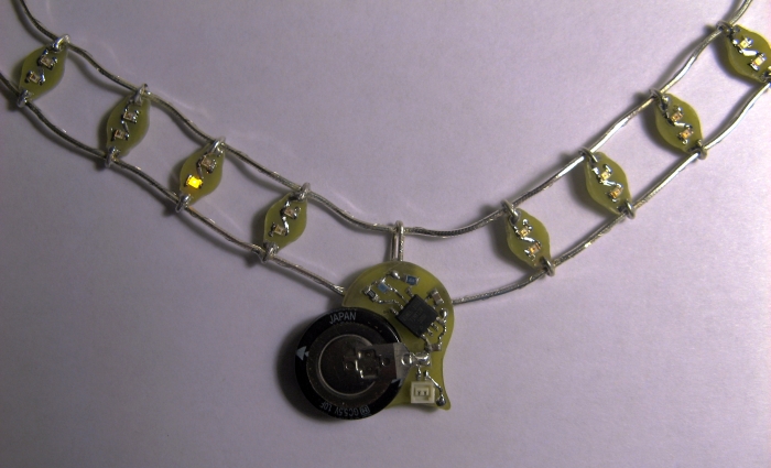
The master module board is in the shape of a heart (seen in the photo in the title of the article), and one of the
Hands - from the sheath!
From words to deeds, to make all this beauty you will need:
- Two silver chains. It is better to take not the usual, from the rings, but round ones in cross section, similar to a cord (gentlemen, jewelers, tell me, how is this weaving called?).
- A bit of silver (or silver) wire, diameter 0.5 - 1.0 mm.
- Textolite foil double-sided, 1.5 mm thick. Even trimming is suitable.
- Laser printer, iron and ferric chloride. If you are closer to technology with a photoresist - you know what to do.
- ATTiny13V controller, in a SOIC package. With the letter V, ordinary ones do not work at low voltage. Tiny13A is even better, it is a later model.
- DS2413, 10 pieces. You can take more or less, not fundamentally.
- SMD LEDs in two different colors. I used green and orange. White and blue I do not recommend taking, for their work requires a higher voltage (up to 4 volts), the ionistor will sit down a bit, and they will no longer shine. It is better to take with a margin in quantity, LEDs like to burn from static at the most inopportune moment.
- Ionistor 1F 5.5V.
- Resistors, SMD capacitors in stock. You can not buy, and take any old card (for example, from a CD-ROM), and drop out.
- Small connector. For example, the connectors that a speaker is connected to on the board in some mobiles are suitable. You can also take a micro connector for the antenna from some WiFi / Bluetooth / GSM device.
Making beads
All boards are made by laser-iron method. I will not paint it in detail, it was discussed here earlier. We print the board on glossy paper, transfer it to textolite with an iron, then pick up with ferric chloride, wash off the toner with acetone, fix the charge, and drill holes.
Beads are made immediately for 8 pieces on one board. Then we cut the board into pieces, reject the unsuccessful ones, with the remaining file we give the desired shape. Photos with blanks at different stages:

Jumpers between the sides of the board are made of wire. After soldering components bead looks like this:

Before stringing the beads on a chain, you need to check their performance and (ATTENTION!) Read the addresses sewn into each chip, because after connecting all the modules to one bus, this will be more difficult. If you have a 1-Wire adapter, great. If not, you need to take the controller, program to read the addresses and connect in turn to each bead. More on reading will be discussed in the second part.
Manufacturing lead module
The charge of the master module is done in the same way, using a laser and iron method. After washing the toner and before tinning, the contours should be transferred to the board, along which we will cut it. We print the contour on glossy paper, apply it to the board, align it with the marks, iron it, wash the paper with water. Then carefully drill the hole along the contour:

Break off excess pliers:

We finish with files:

Ready board after soldering components, from above:

and below:

Please note that the board does not provide any connections for the programmer, so the controller must be flashed separately and installed on the board at the very last moment.
Assembly
The beads are attached to the chains as follows: we make brackets from silver wire and solder to the chain in the places marked in advance. We use for this relatively refractory solder, I took lead-free (Sn 95 Ag 5).


Similarly, the lower chain is being prepared, only the intervals between the brackets should be slightly larger, so that after the assembly a semicircle is obtained.
Beads are soldered already to the brackets, and using more low-melting solder (you can use the usual POS-60) and a soldering iron with a thermostat so that the whole structure does not solder off the chain. The contact must be both from the front side of the board, and from the wrong side. It is important not to confuse the top and bottom. The contact where the anodes of the LEDs go is the top, soldered to the long chain.
The free ends of the lower chain need to be attached to the top, but so that there is no closure. For this purpose, we cut out two small textolite triangles, cut the foil on each into two sites (it was already too lazy to print and etch these little floats), after which we soldered to the chains with familiar brackets.
We hang a heart on the top chain in the middle, with the help of a wire loop. The ends of the lower chain are simply soldered to the contact pads.
All collected, checked again, washed with alcohol from flux residues. Pictures are clickable:


Charger
Well, the device - it says loudly. The circuit charges from the USB port through a 47 ohm resistor, limiting the initial current pulse. Up to 3 volts, the ionistor charges in five minutes, fully - about half an hour.

Be careful, rake!
During the assembly and debugging revealed two unpleasant circumstances. Firstly, the chain, although silver, carries a very bad current, the presence of dozens of joints affects. The signal does not reach extreme beads any more. I had to take a thin (0.15 mm) silvered wire, twist it neatly around the chain and solder to each module. From a distance of a meter, this wire is no longer visible.
Second rake: when the supply voltage is very slow, the controller refuses to start. I do not know, this is a feature of all AVR-ok or just my specimen. It was discovered at the very last moment, when everything was already assembled, stitched and unsoldered. It was necessary to put a micro-button on the back of the board, which short-circuits the ionistor. With a short press, it does not have time to discharge due to its internal resistance, but a pulse appears in the power circuit, which is enough to start the controller. If someone will build a similar design, do not repeat my mistakes, immediately put the RESET button.
Drawings of boards in Eagle, as well as ready-made templates for printing in one archive:
nekaka.com/d/oDpQyHL9CY
Finally, the video work. This is a test firmware that checks all LEDs. The final version will be a little with other effects.
The second part of the article will be devoted to writing firmware for the controller. To be continued.
Source: https://habr.com/ru/post/128891/
All Articles