We develop horizons and immerse ourselves in robotics
Electronics is very interesting. A very pleasant feeling when you open an electronic device, you see something familiar: “Here is a diode, but a transistor!”, When instead of carrying the motherboard for repair, you can change the capacitor on it in a couple of minutes . However, many people are afraid of it, presenting huge wiring diagrams with strange squiggles and incomprehensible assembly code. I want to show everyone that it’s easy to start engaging in electronics, and in particular robotics! A simple robot can be made in just a couple of hours.
Few words
In these articles, I will step by step make the robot, starting with the simplest, and gradually complicating, and describe the various nuances, the solution of problems that will meet me on the way.
First of all, these articles are written for newbies to help them get their first experience in this field in a positively pleasant way, so that everything will work out for them and they will not fall into despair.
Those who understand, I will ask not to criticize strongly about some moments where something can be done better and more rationally, but to give advice.
Enjoy your reading.
From the lyrics to the case
The first goal is to build a base for the robot and make it ride.
We will need:
• Microcontroller (further mk)
• one-side glass fiber laminate
• 2 electric motors
• Anything as wheels
• Programmer for firmware mk
• Optionally, for convenience, a connector for connecting the programmer to the board
')
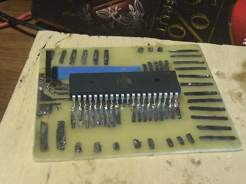
I began to learn Atmel's AVR controllers, because they are fairly common and simple, and I will use them. In this case, my choice was ATMega16A.
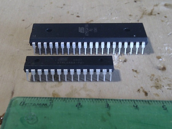
(In the photo ATMega16A and ATMega8A)
It has 40 legs and 16 kb of memory. This is more than enough for my experiments and the voracious C code. Yes, I will program in C, since it is still simpler, but I honestly learned the very basics of the assembler, which I advise others to do: it will help immensely in the future. You can use other microns, for example, atmega8.
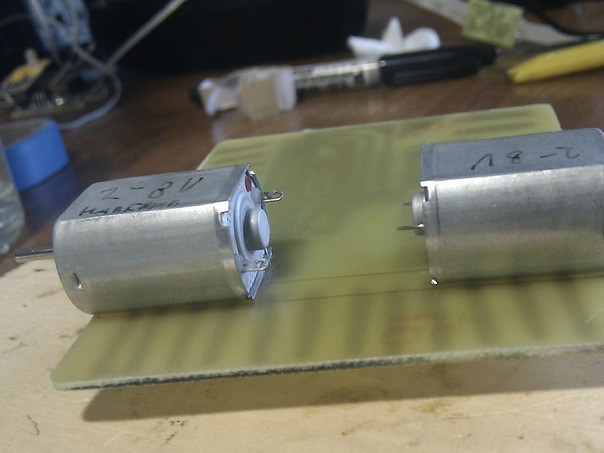
I took the motors designed for a voltage of 2-8V with a current of 120mA.
Step 1. Base
We need to make the main board. We will etch the PCB. How to do this has been described many times.
First of all, I need to separate the tracks under the programmer. I have already prepared in advance the programmer of the construction of Gromov, who works via the com-port.
By the way, right away he did not earn from me. The reason was in non-compliance with the polarity of the diodes, pay attention to it.
Look at the location of the I / O ports:
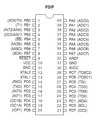
We need to tie the legs like this (in the order of the programmer connector):
- 7 -> MISO
- 8 -> SCK
- 11, 31 -> GND (0V)
- 9 -> RESET
- 6 -> MOSI
- 10, 30 -> VCC (+ 5V)
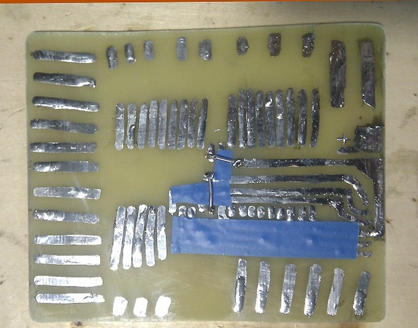
I do not have a laser printer, so I will use a regular black marker. Its disadvantage is that it is partially washed off and because of this it is impossible to make thin tracks. And, of course, everything is drawn by hand. We draw:
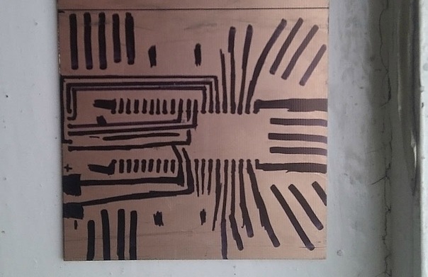
Wiring is not perfect, we will need jumpers, but oh well. I also brought contacts from all the legs of the micron, so that in the future it would be more convenient to solder to them, and made tracks on the board, maybe useful, not to waste the valuable metal of the PCB.
I persecute in a solution of copper sulfate and salt. Pros in availability, price, much less toxicity. Potential minus in the speed of the process.
I spread the mixture and put the board there. It is desirable to move it, so the process will be faster. You can put there a spray aquarium compressor.
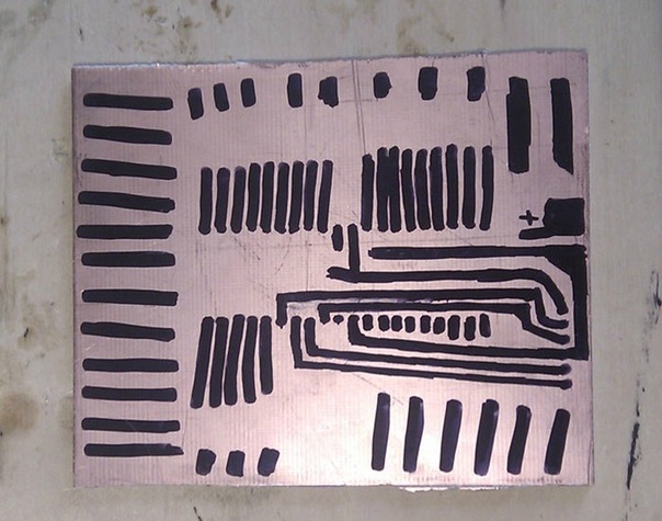
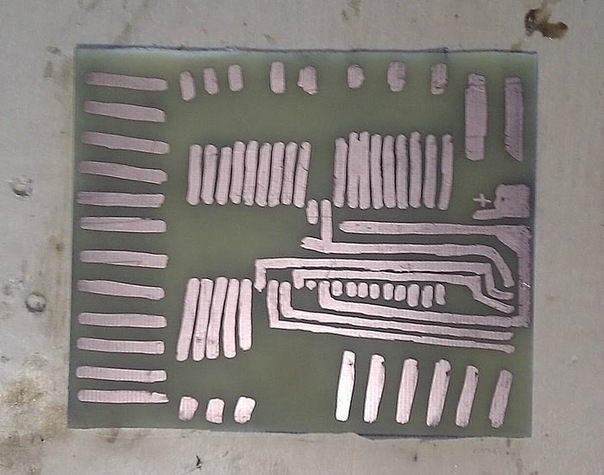
This time the persecution lasted a very long time, for two or three hours. Because the concentration in the solution was weak: it has been with me for several weeks and slowly precipitates. The board turned out to be very unsuccessful, a large percentage of the tracks were washed away and missed.
Hence attempt number two.
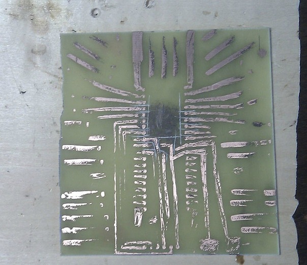
We draw again, a little differently, several times carefully drawing tracks with a marker. But most importantly (!), We degrease the board before it, which I forgot to do in the first attempt.
But the subtlety: how to poison very quickly. We place the board in an airtight container with a solution (it is not necessary that it covers all of it). We are closing. And we begin to actively shake this container with our hands. As a result, my board got corrupted in just 3 minutes of such actions. And here is the result:
This time it came out very high quality.
After tinning, solder the jumpers using electrical tape to overlap the tracks.
Solder the chip and the connector under the programmer. Done:
Step 2. Movement
We organize the moving part. The system will be on three wheels, two of which are driven by engines. I decide to simply glue them to the PCB.
We mark, degrease the board with a cotton swab and alcohol-containing liquid.
We glue the engines, leave them dry.
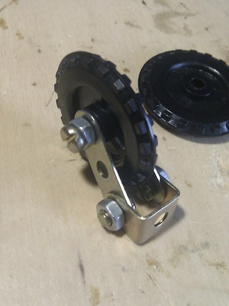
We come up with a third wheel. I found an old children's mechanical constructor, which is ideal and assembled this design:
Just put it on the glue and leave to dry.
Next we need the wheels themselves. I decided to take them from the same set. However, the holes in them are much larger than the diameter of the shafts of the engines. Therefore, the creative with wire and elastic was used:
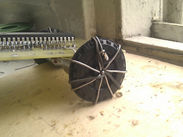
Solder the contacts of the engines with wires to the feet on the microns. Let it be PB3 and PB4, for the left and PA3, PA4 for the right.
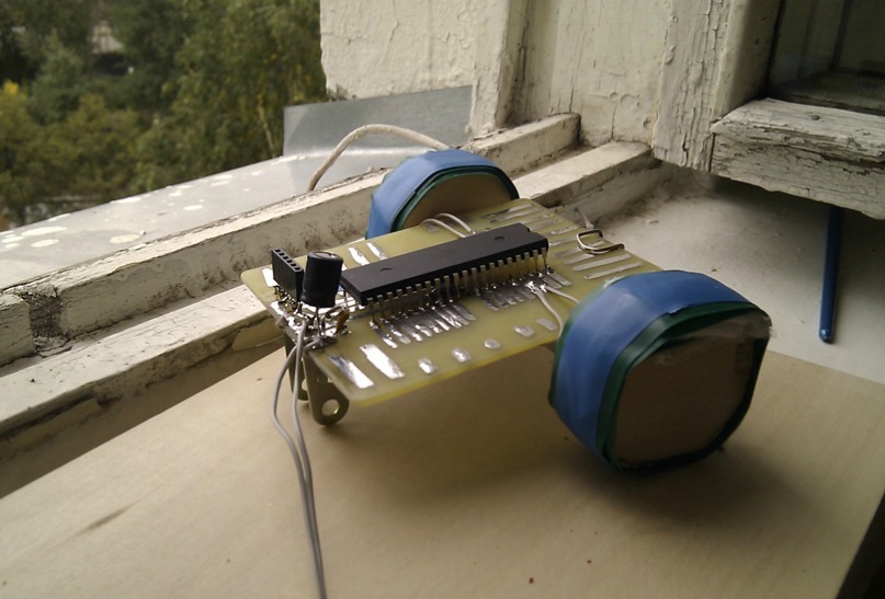
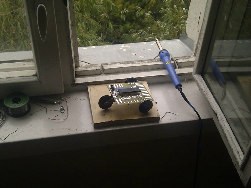
The first version of the robot is ready:
Step 3. Program and firmware.
I wrote a straightforward C program that just starts the engines.
#include <avr/io.h> // - int main(void) { // DDRB |= (1<<2); // PB2 DDRB |= (1<<3); // PB3 DDRA |= (1<<2); // PA2 DDRA |= (1<<3); // PA3 // // PORTB |= (1<<2); PORTA |= (1<<3); // PORTB &= ~(1<<3); PORTA &= ~(1<<2); return 0; } I'm flashing with uniprof.
We connect microns, we supply power (I took 5v from the computer power supply).

Mk responded immediately.

Take the firmware HEX-file and sew. Initially, one bit did not want to flash, but the “brake” button decided everything.
Is done. Turn off the programmer, reset the reset with a finger and ... nothing.
Step 4. Cruel Reality
Here is the first sudden problem:

Why so? After all, we have a high level of 5V, and a low 0. We begin to study the materiel and forums.
And here we learn that the micron can only deliver a current of 40-50 mA maximum, which is not enough for our engines of 120 mA. Accordingly, we can apply, for example, transistors.

But it is even easier (we are newbies, yes) to get a ready-made engine driver (hereinafter referred to as dd).
I bought the popular l293d.

You need to connect the motors to the Output legs, and in the Input legs there are microns, which will control the corresponding Output outputs (by number). Enable1 and Enable2 must be powered up plus.

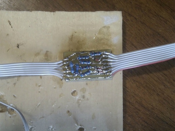
We poison, puddle, solder dd:

Sticking board on our robot.
We unsolder the wiring from micron to the engines and solder them to the corresponding contacts of our driver.

And that's it!
We connect to the programmer and it should work. If not, check the soldering sites for defects and unnecessary contacts. (It didn’t work right away. When I connected the power, the system began to warm up terribly. I thought that the problem with the heat sink from l293d even soldered a couple of solder wires to it, which did not help. Studying the forums, I soldered 2 capacitors (one electrolyte per 100 microfarad and one Ceramic at 0.1 microfarad) parallel to the power supply, did not help either. As a result, it turned out that I just confused the plus and minus on the power connector from the bp).
Earned? Fine. We take our program, flash, reset resets, and hurray! Engines work stably!
The old wheels fell off, so I cut new ones out of wood, and since They came out not quite round, slightly smoothed their wonderful tape.
Total:

Now a solemn moment!
Yes!
Let's play a little with the movement:
#include <avr/io.h> #include <util/delay.h> int main(void) { DDRB |= (1<<2); DDRB |= (1<<3); DDRA |= (1<<2); DDRA |= (1<<3); unsigned char i= 0; while(i<3){ // PORTB |= (1<<2); PORTA |= (1<<3); PORTB &= ~(1<<3); PORTA &= ~(1<<2); _delay_ms(700); // PORTB &= ~(1<<2); PORTA &= ~(1<<3); PORTB |= (1<<3); PORTA |= (1<<2); _delay_ms(1100); i++; } while(1) { // , PORTB |= (1<<2); PORTA &= ~(1<<3); PORTB &= ~(1<<3); PORTA |= (1<<2); _delay_ms(3000); // , PORTB &= ~(1<<2); PORTA |= (1<<3); PORTB |= (1<<3); PORTA &= ~(1<<2); _delay_ms(3000); } return 0; } Afterword
As you can see, make the simplest robot elementary. Further, all is limited only by your imagination.
Do not be afraid to start something new - everything will definitely work out.
If you have questions - ask.
Thanks for reading!
FAQ from replies to comments on the topic
About the cost price:
- ATMega16A to DIP ~ 110p
- 2 engines QX-FF-130-14230 ~ 140r
- l293d ~ 60r
- Capacitor 100mkF 25V ~ 2p
- Ceramic condenser 0.01µF ~ 2p
- Textolite ~ 30p
- Nest under the programmer ~ 5p
Total: ~ 349p + optional: solder, wires, wheels, glue.
Engines can take other, cheaper, at least for 20r.
UPD:
Many thanks for the comments. Very nice.
Source: https://habr.com/ru/post/128793/
All Articles