Development of a virtual system "Multimeter" based on National Instruments
Objective
Develop a system for measuring DC and AC current and voltage, as well as resistance using the tools of National Instruments, namely using the DAQ information acquisition system.
The developed system should allow analyzing measurement results using a computer, as well as synchronizing data with a computer for further analysis.

Solution Description
Consider the functional diagram of the system in Figure 1.
')
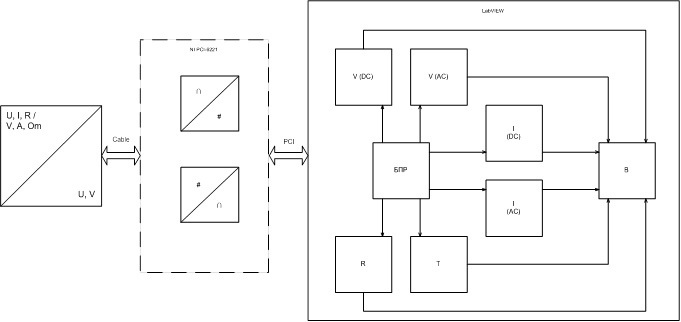
Figure 1 - Functional diagram
Developing a multimeter system, I divided it into 3 blocks:
- The measuring transducer , which provides the output voltage proportional to the measuring value, as well as provides the ability to switch measurement ranges.
- Information collection system . The paper uses the National Instruments PCI-6221 data acquisition system. The criterion for choosing the system was the presence of a built-in DAC (digital-analog converter) and ADC (analog-digital converter). The system provides data transmission via the PCI bus.
- The software part of the virtual system "Multimeter" was written in the graphic language LabVIEW from the company National Instruments.
To remove data and switch ranges - a transmitter circuit was developed (Figure 2).

Figure 2 - Electrical schematic diagram
A National Instruments based multimeter can measure voltages from -100V to + 100V. Since the PCI-6221 allows you to relieve the voltage from -10V to + 10V, a range switch is designed.
A shunt resistor was used to measure the current. The data acquisition device perceives a voltage drop across it and, according to Ohm’s law, calculates the strength of the current.
Implemented the ability to measure resistance. For this purpose, the DAC is used. Since the information collection system cannot serve as current sources, we will use a precision resistor. After that, DAQ will remove the voltage drop across the measured resistor and, according to Ohm’s law, calculate its resistance.
On the basis of the principle board, a printed circuit board was developed.
Labview
When designing the front panel of the device, emphasis was placed on usability. The program requires LabVIEW software installed on a PC. It contains elements such as: output of the measurement result, a prompt area in which additional information about the measurement is displayed, a panel for selecting the type of the measured value, a panel for selecting the measurement limit, as well as an output for additional signal characteristics.
The block diagram (Figure 3) shows the decision block with the block listing expanded for measuring DC voltage, the NI-DAQmx VI driver is used. After selecting the measurable quantity and the measurement limit, the data acquisition system reads the data.
The DAQmx Create Virtual Channel block creates a virtual channel Analog Input Voltage that is capable of sensing analog input voltage.
After that, the DAQmx Read block reads the data. The obtained value of the measured voltage is fed to the decision block, further analysis of the signal is carried out.
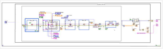
Figure 3 - LabVIEW Chart Block
Conclusion
As a result, a multimeter device based on National Instruments was developed. In the future, it will be possible to save data, notify the operator of unwanted data changes, automatic reporting and so on.
When developing a virtual system, NI literature was used, and consultations were held with representatives of NI in Ukraine.
Literature
1. V.P. Fedosov Digital Signal Processing in LabVIEW. Moscow .: DMK Press, 2007. - 456 p.
2. E. V. Sviridov, Ya.I. Listratov, N.A. Vinogradov Application software development in the LabVIEW environment. Moscow .: Publishing House MEI, 2005. - 50 p.
Source: https://habr.com/ru/post/128382/
All Articles