Little known MST. Multi-region implementation considerations

Denial of responsibility.
This article will discuss the logic of choosing a Root port on switches that play the role of CIST Regional Root in the multi-regional implementation of the MST protocol. In the case of using practical advice and criminal conclusions from this article in the production networks of enterprises, the author is not responsible for your subsequent actions, possible failures in the functioning of the computer network, partial data loss and damage to equipment.
')
Introduction
As part of the familiarization with the MST protocol, I had to deal with the fact that on the Cisco Systems website the information about the protocol is not much wider than in the CCNP SWITCH 642-813 I admired in the Talmud (the main task of which, I think, to reduce the number of CCNP by the labor market, freeing up jobs for the children of the great Ganges), and speaking directly from the links www.cisco.com/en/US/tech/tk389/tk621/technologies_white_paper09186a0080094cfc.shtml - Understanding Multiple Spanning Tree Protocol (802.1s) www.cisco .com / en / US / tech / tk389 / tk621 / technologies_tech_note09186a0080094366.shtml - Configuring MST (802.1s) / RSTP (802.1w) on Catalyst Series Switches Running CatOS
The reader will have the same vata as in the product of Native American creativity with an Indian name (no, I'm not talking about Mithun Chakroborty, but about David Hucaby), mentioned earlier.
In addition to the above links, I managed to find another article on the Cisco site that gives answers to at least some questions - this is www.cisco.com/en/US/docs/switches/datacenter/nexus5000/sw/configuration/guide/cli_rel_4_0_1a/ MST.html - Cisco Nexus 5000 Series NX-OS Software Configuration Guide - Configuring Multiple Spanning Tree . From this document, at least, it turned out to extract sensible definitions of the terms CST, CIST, IST, MSTI, which, before that, caused me considerable difficulties.
Act 1st. Scene 1st.
But there were still more questions than answers to the BPDU format, MSTP messages, switch interactions, selection algorithms and other important aspects of the protocol operation. Entering into a rage, I turned to the original source, but I already faced a diametrically different problem - the amount of information in the draft clearly exceeded my modest requests, and combined with the methods of its presentation, a thoughtful reading of the entire document threatened me with a partial loss of understanding and joining the standard to the working group on altruistic basis. As a result of the ongoing search for material and spiritual peace, I found a really valid article, the notorious Peter Lapukhov (4xCCIE) - Understanding MSTP .
The absolute majority of my questions disappeared after reading, the tears of joy irrigated the unshaven face of the veteran, but ... carefully looking at all the topologies used in the article noticed one nuance - all the Regional CIST Roots are connected to the region in which the CIST ROOT is located through just one link. Below, Figure 1 shows an exaggerated version of this topology.

Fig. one
Remembering the tasks set before the article (something about Root ports) and looking at this topology, there are no questions - the choice of the Root port is simple and obvious. Regional Root (SW2) selects and uses its best port to CIST Root (SW1) as the Root port, the rest of the boundary ports towards the CIST Root are blocked on it, and on the other switches in this region, the boundary ports become either Designated or Altn - depending from whether they send the best BPDU or not for the segment - everything is as with RSTP (elementary Watson).
In case of using multiple parallel links with the same price (with different CIST Regional Root will use a link with a lower price - this algorithm is described in detail in all MST documents - yes yes, even in Mithun) CIST Regional Root will select the Root port as if Another protocol of the STP family - based on Lowest sender port ID .
But what will be the basis for choosing the best BPDU if the CIST Regional Root connects to the CIST Root region via several links to different switches with the same price (Fig. 2 - CIST Root is now SW2 and located in region 23).
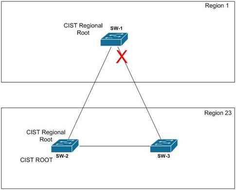
Fig. 2
It would seem - well, there is a well-known algorithm:
All tiebreaking STP decisions are based on the following sequence of four conditions:
- Lowest root bridge ID
- Lowest root path cost to root bridge
- Lowest sender bridge ID
- Lowest sender port ID
Well, then use it, be happy, grow children, love family. But we are already guys not from the street, we already know the principles of constructing a CST, we know that - “However, an excerpt from Understanding Multiple Spanning Tree Protocol (802.1s) . And also read and Lapukhov, that
<When a switch is up, it’s declaring it’s going to be outgoing BPDUs. If you’re not happy, you’ll find out what to do. This is a region of the region's internal ports.
For clarity, I will give the BPDU format so that it is clear which fields are transmitted, which are not (what fields mean to find can be found on the above links, and the picture itself is taken from the article by Peter Lapuhov - not an advertisement !!!)
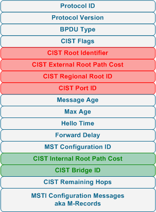
Fig. 3
So, the first 3 points of the algorithm seem to disappear - the Root Path is the same under our conditions, and according to the sender bridge ID, both BPDUs are the same and equal to CIST Root ID. The fourth item remains - Lowest sender port ID. Hmm ... Quite ambiguous - how to compare the Port ID of BPDUs coming from different switches. At this point, thoughts about Port ID counting algorithms for the BPDU leaving the region got into the head as the sum of the Port ID from the BPDU of the port created on CIST ROOT and Port ID boundary. Or the option of maintaining Port ID CIST Root while passing BPDU through the region (and if the first option still seems to me to be sound, then the second one, of course, does not hold up to criticism - since the first parallel links and hello will not break the tie). But everything turned out to be much more prosaic, as shown by the
show spanning-tree mst detail - only the switch port from which this BPDU was sent to BPDU, regardless of whether CIST is ROOT or ordinary BRIDGE. And as a logical consequence, a change in the port ID, whether by physically switching links or changing the port-priority , did not produce any results.SW1#show spanning-tree mst
##### MST0 vlans mapped: 1-9,11-19,21-4094
Bridge address f025.724e.ac00 priority 32768 (32768 sysid 0)
Root address f025.7250.9800 priority 0 (0 sysid 0)
port Gi0/18 path cost 20000
Regional Root this switch
Operational hello time 2 , forward delay 15, max age 20, txholdcount 6
Configured hello time 2 , forward delay 15, max age 20, max hops 20
Interface Role Sts Cost Prio.Nbr Type
---------------- ---- --- --------- -------- --------------------------------
Gi0/18 Root FWD 20000 128.18 P2p Bound(RSTP)
Gi0/37 Altn BLK 20000 16.37 P2p Bound(RSTP)Since I didn’t see any sense in going up through the list of tiebreaking STP decisions - everything was pretty obvious and unequivocally written in these of your Internet (see the explanation in the previous paragraph), I decided to try the option of changing the new Max-hop parameter that replaces the MST timer Max-Age (only until the moment of interaction with other variations of STP!). Indeed, the BPDUs coming from SW3 have this parameter 1 less than the BPDUs coming from SW2. But here, too, shame and all kinds of fiasco awaited me. = (
Well, let's take a look at the output of
show spanning-tree mst detail once again and more carefully:SW1#show spanning-tree mst 0 detail
##### MST0 vlans mapped: 1-9,11-19,21-4094
Bridge address f025.724e.ac00 priority 32768 (32768 sysid 0)
Root address f025.7250.9800 priority 0 (0 sysid 0)
port Gi0/18 path cost 20000
Regional Root this switch
Operational hello time 2 , forward delay 15, max age 20, txholdcount 6
Configured hello time 2 , forward delay 15, max age 20, max hops 20
GigabitEthernet0/18 of MST0 is root forwarding
Port info port id 128.18 priority 128 cost 20000
Designated root address f025.7250.9800 priority 0 cost 0
Design. regional root address f025.7250.9800 priority 0 cost 0
Designated bridge address f025.7250.9800 priority 0 port id 128.18
Timers: message expires in 4 sec, forward delay 0, forward transitions 7
Bpdus sent 5917, received 50941
GigabitEthernet0/37 of MST0 is alternate blocking
Port info port id 128.37 priority 128 cost 20000
Designated root address f025.7250.9800 priority 0 cost 0
Design. regional root address f025.7250.9800 priority 0 cost 0
Designated bridge address f025.724e.c780 priority 32768 port id 16.37
Timers: message expires in 5 sec, forward delay 0, forward transitions 14
Bpdus sent 5842, received 56720
Op-pa ... We draw attention to the lines with the Designated bridge address . Sharpen ... Sharpen ... Everything !!! Harosh pointy! So, all the same information about the internal topology is transmitted to the outside. Out of idle curiosity, we launch WireShark and compare the BPDUs received on the two ports of the SW1 switch (here I only give one BPDU with marked differences with the second):

Fig. four
So the differences:
- Port identifier
- CIST Internal Path Cost
- CIST Bridge Identifier (and their ilk respectively)
- Max hop
And since the fact that Port Identifier and Max hop do not affect the choice of the best BPDU, we have already found out we have two suspects - CIST Bridge Identifier and CIST Internal Path Cost. And it is worth noting that we already saw the CIST Bridge Identifier in the
show spanning-tree mst detail .Well, what to do - we will check these two parameters, nothing else remains - the rest of BPDUs are identical. But, the used topology is not suitable for verification, CIST Root is located on the border of the region and sends BPDU to SW1 itself, so the CIST Bridge Identifier is always better than any other in the region (because of the best CIST Bridge Identifier among the switches of all regions, it was chosen) and the CIST Internal Path Cost parameter in its BPDU will always be zero.
Consequently, CIST Root must be removed from the region’s boundaries and the topology is converted to the following:
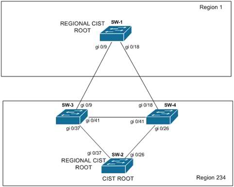
Fig. five
According to the results, after changing the topology, the roles of the ports on SW1 remained the same -
Gi0/18 Root; Gi0/37 – Altn. Gi0/18 Root; Gi0/37 – Altn.SW1# show spanning-tree mst 0
##### MST0 vlans mapped: 1-9,11-19,21-4094
Bridge address f025.724e.ac00 priority 32768 (32768 sysid 0)
Root address f025.7250.9800 priority 0 (0 sysid 0)
port Gi0/18 path cost 20000
Regional Root this switch
Operational hello time 2 , forward delay 15, max age 20, txholdcount 6
Configured hello time 2 , forward delay 15, max age 20, max hops 20
Interface Role Sts Cost Prio.Nbr Type
---------------- ---- --- --------- -------- --------------------------------
Gi0/18 Root FWD 20000 128.18 P2p Bound(RSTP)
Gi0/37 Altn BLK 20000 128.37 P2p Bound(RSTP)
But so far it does not mean anything, because with equal default values of 32768, the SW-4 has the lowest MAC. Increase the priority value on SW-4 to 40960 and study the output
sh spanning-tree mst 0 detailSW1#sh spanning-tree mst 0 detail
##### MST0 vlans mapped: 1-9,11-19,21-4094
Bridge address f025.724e.ac00 priority 32768 (32768 sysid 0)
Root address f025.7250.9800 priority 0 (0 sysid 0)
port Gi0/37 path cost 20000
Regional Root this switch
Operational hello time 2 , forward delay 15, max age 20, txholdcount 6
Configured hello time 2 , forward delay 15, max age 20, max hops 20
GigabitEthernet0/18 of MST0 is alternate blocking
Port info port id 128.18 priority 128 cost 20000
Designated root address f025.7250.9800 priority 0 cost 0
Design. regional root address f025.7250.9800 priority 0 cost 0
Designated bridge address 0027.0c0e.e900 priority 40960 port id 128.18
Timers: message expires in 4 sec, forward delay 0, forward transitions 7
Bpdus sent 5917, received 52386
GigabitEthernet0/37 of MST0 is root forwarding
Port info port id 128.37 priority 128 cost 20000
Designated root address f025.7250.9800 priority 0 cost 0
Design. regional root address f025.7250.9800 priority 0 cost 0
Designated bridge address f025.724e.c780 priority 32768 port id 16.37
Timers: message expires in 4 sec, forward delay 0, forward transitions 14
Bpdus sent 42, received 88169So, the change in CIST Bridge Identifier finally gave the long-awaited results - the decision on choosing the best BPDU was changed. In spite of this, the variant with a change in the CIST Internal Path Cost was also checked, but it, like its earlier predecessors, turned out to be ineffective. According to the WireShark logs, the changed Internal Path Cost value was transmitted, but did not affect the choice of the best BPDU.
Summary.
This article is not intended to acquaint the reader with the basics of the MSTP protocol, rather the opposite - the reader should already be fairly aware of the properties and logic of the protocol - documents that are suitable for familiarization are given at the beginning of the article. The only question it reveals is the logic of choosing the best BPDU for CIST Regional Root when connecting it to the region where CIST Root is located, through several non-parallel links (to different switches) with the same price. It was possible to influence this only by changing the CIST Bridge Identifier on the switches from which the links go, and provided that CIST Root is not one of these boundary switches (I’ll clarify once again that the price on the links is the same; ). The final tiebreaking algorithm for selecting the best BPDU for the topology in question consists of:
- Lowest Root bridge (here, here and the link price change - and you asked!)
- Lowest CIST Bridge Identifier
Since in the materials I read, the second item of the mechanism was not mentioned anywhere, and even vice versa it was noted that the internal information about the regional switches (including CIST Bridge Identifier) is not transmitted / not used outside the native for the switch region, its (item) the search took a lot of time and resulted in a whole poem.
Source: https://habr.com/ru/post/128172/
All Articles