We update the sketch by air
 In the process of developing code for Arduino compatible boards, it is often necessary to update the firmware in the controller, very often it is difficult to do this, because the device is already assembled and pulling shield and heaps of wires back and forth - it becomes tiresome and annoying. My first Arduino was a kit of parts (assemble it yourself) Freeduino Through-Hole, the kit upon arrival was immediately soldered and tested, but in this analog of Arduino Diecimila there was one nice detail missing ... namely, an automatic switch of the power source, in my case it was suggested to poke the jumper on the board, which further complicated updating the sketch for my
 In this post I will describe how in 5 minutes with a soldering iron to modify the XBee Shield to update the sketch via a wireless communication channel. You can also project these changes to other XBee Shield counterparts without too much difficulty.
To begin with, I had two XBee Shields, the difference was that one of the shields had a mini-usb connector and an FTDI USB-Serial chip for directly connecting the XBee module to a PC, so they bother with third-party USB-Serial cords for me did not have to. As it turned out, working with modules through this shield is very convenient, the RTS and DTR pins were divorced where necessary, the firmware was updated, configs were flooded. Attention! If you try to update the firmware without connecting pins, RTS and DTR, the module will brittle, but this is fixable. It is necessary only to specify the API mode of working with the module in the X-CTU connection settings and update the firmware again.
')
And so proceed:
1. Modification of the transmitting module
Let's start with iron. In my case, the transmitting label has undergone minor and at the same time
Go to the settings of the module itself. If you have used XBee modules at least once in your handicrafts, then you are most likely already familiar with the X-CTU program and its capabilities. About setting up with it further and will be discussed.
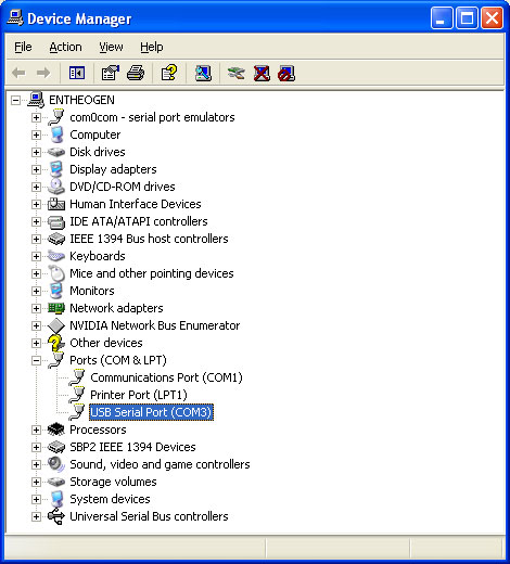
The first thing we need to do is connect our XBee module to the computer and check the connection. If you are doing this for the first time, then the parameters will be as follows (the COM port should of course choose your own):
After setting the parameters, click " Test / Query " and after a second in response you should receive a message with the serial number and model of the module.
If this does not happen - then somewhere there is an error. As an option, try to cross the port speed (Baud).
Go to the Modem Configuration tab and click Read to get the current settings and the firmware version of the module.
The first value that we change is PAN ID.
PAN ID consists of 4 digits in HEX format and will determine the ID of the network in which this module will work. The PAN ID must be the same on both the receiver and transmitter. It is also recommended not to configure any more modules on this ID in order to avoid conflicts.
The next item in the settings should change the speed of the port. It should correspond to the speed necessary for the firmware of a specific chip (there are also alternative loaders that increase the speed of the firmware). For a 168 chip, this is 19200, and for a 328p 57600. Note that to work with the module in the future, you need to make corrections to the sketch (for example, if you used the standard 9600 speed before), change the speed of work with the port.

Packetization Timeout - timeout that determines how long to wait before being broadcast. May require a value greater than 10 - is selected individually based on the size of the sketch, 10 = 10kb sketch.
Now set the D3 pin (Digital Input / Output) to the 3-DI position, which means that the pin will be used as a digital input.
Set the parameter Digital IO change detect to FF. You can also specify instead of FF, 0x08. Then we specifically point out that the changes in DI need to be heard on the D3 pin, but it works fine as well.
Now the transmitter (transmitter) is configured to send the current D3 pin status to any modems within reach. We will write the changes to our module by clicking the Write button on the top panel.
And it is also worth mentioning the predictable rake of Windows users (in MacOS and Linux this is provided by default).
It is necessary to specify the Set RTS on close option in the COM port settings (a different name is possible in the Russian version)


Make sure the box is checked and apply the settings.
2. Modification of the receiving module
We will begin the modification according to the tradition with iron, namely, we solder into a heap (so far better on weight for further debugging of the circuit) a capacitor, a transistor and a resistor according to the following scheme:

Reset signal from XBee - leads directly to D3 pin. Reset to Arduino - directly to the Reset pin on Arduin.
You should get something like this.

I will repeat just in case, do not forget to adjust the exchange rate in your project.
Now we connect the receiver (receiving module) to the computer and open the already familiar X-CTU to set the following parameters
PAN ID - Must match the transmitting module
Interface Data Rate - Must be the same as the transmitter.
Packetization Timeout - also as I understood it is similar to the transmitter
Set the pin D3 of our receiver 5-DO HIGH (Digital Out Default High)
I / O Output In Disabled. To prevent status messages from entering the serial port
And finally, we set the I / O input address to the FFFF - to receive I / O messages from all broadcasters. You can also specify the address of the transmitter.

Now we write the changes to our module by clicking the Write button.
I recommend once to configure and save profiles for both modules on your computer in order to avoid confusion in the future. Top Profile -> Save.
Do not forget to connect all the GND together and connect the transmitting module to the computer (via an adapter or label) and install the receiving on the target Arduino. Once again we check everything, suddenly I was mistaken or some other trifle remained where. We check everything quickly with a glance again and you can try it! :)
The rakes that I had: The sketch refused to flood, although the Arduino sometimes rebooted, it put me in a stupor, but it soon became clear that if you quickly click twice on the Upload in the IDE, the Arduino sketch was successfully flooded, though not always (I blame Wifi and Blutooth around there was a lot) Apparently it’s worth digging in the direction of the condenser (playing with volume) Well, or in extreme cases, edit the IDE code so that the RTS pin itself jumped twice :)
I apologize for the confusion, I began to write satatiya almost a year ago, I have already forgotten a lot, but said everything that I wanted to say. Suggestions and suggestions are welcome. Inaccuracies in the article or errors according to tradition, write in a personal, I hope the article was useful to you.
My article can be considered a translation of this
I just added a bit and embellished where I could.
My question in Q & A is here and thanks to the respondent djmorgan
Source: https://habr.com/ru/post/126539/
All Articles